413
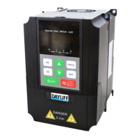
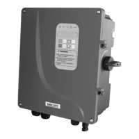
Step 3: After finishing the wiring, tighten the bottom waterproof PG terminal with a
tightening torque of 7Nm and lock the upper cover. Fix the earth cable to the ground
screw at the bottom of the housing.
Fig 6: Wiring Diagram
Fig 7: Shell Grounding Operation Diagram
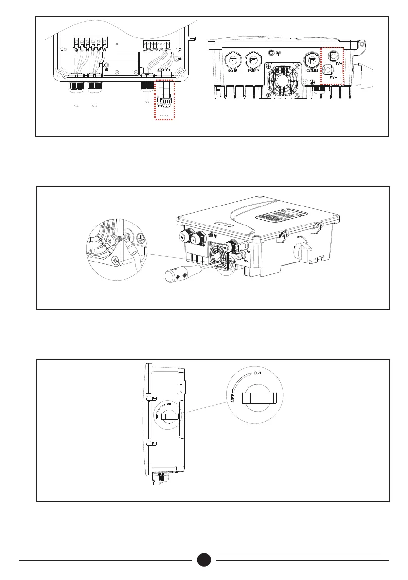
Step 4: Turn the knob of the DC disconnect switch on the right side of the inverter to
“ON” position as shown in Fig 8, solar power supply then is connected and inverter
starts.
Fig 8: DC Disconnect Switch Operation Diagram
 Loading...