412
3.5 Electrical Connection
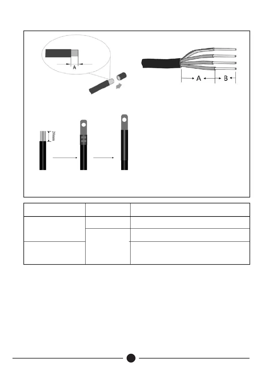
Step 1 : Prepare all the input/output cables as shown in Fig 5.
Step 2: Using the hex screwdriver open the upper cover of the inverter, pass the cable
through the waterproof PG terminals at the bottom. The tightening torque is 0.8Nm for
power terminal and 0.6Nm for the signal terminals. Insert the PV input cable into the
MC4 terminal located at the PV+/PV- position as shown in Fig 6. Note the positive and
negative poles.
Fig 5: Cable Preparation Diagram.
Single Core Cable Stripping
Diagram
Single-Core
Strip 10mm at A
Power Cable
Cable
Type
Process Description
Strip 50mm at A and 10mm at B
Multi-Core
Strip 50mm at A and 5mm at B
Control Signal Cable
Multi-Core Cable Stripping
Diagram
Crimping Diagram
 Loading...