28
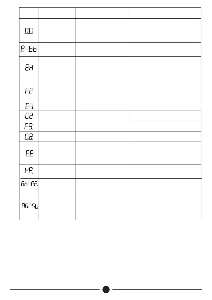
Code Description
Possible Reason
Counter Measures
Warning
Code
Loss of load
protection
Pump dry running
Pump cables all disconnected
Inverter selection does not
match the pump
Inspect water level
Inspect pump cable connections
Inspect if the pump power matches
inverter capacity
All parameters initialization
Refer to the nearest Dayliff dealer for
assistance
Parameter error
Memory chip read/write error
Device or circuit damaged
Output short circuit
to ground
Output cable damaged
Pump motor insulation
damaged
Device or circuit damaged
Inspect cable connections
Inspect pump motor
Refer to the nearest Dayliff dealer for
assistance
Over temperature
of module
Air duct blocked
Too high temperature
Clear the air duct
Improve environmental heat dissipation
condition
U phase CT fault
Device or circuit damaged
Refer to the nearest Dayliff dealer for
assistance
V phase CT fault
Device or circuit damaged
Refer to the nearest Dayliff dealer for
assistance
W phase CT fault
Device or circuit damaged
Refer to the nearest Dayliff dealer for
assistance
DC CT fault
Device or circuit damaged
Refer to the nearest Dayliff dealer for
AC output lose
phase
Motor cable disconnected
Single phase motor is
connected
Device or circuit damaged
Inspect pump cable connection
Modify corresponding parameter
Refer to the nearest Dayliff dealer for
assistance
AC input lose
phase
Three phase power supply
lose phase
Insp ect AC power supp l y ca b le
connections
Tank water level
abnormal
Water level abnormal
Wrong installation or
parameters setting for the
water level switches
Water level switch
damaged or wiring
damaged
Wait for the water level returns normal,
system will begin countdown to restart
Correctly install and set the parameters
according to manual
Change the water level switch, check
wiring
Well water level
abnormal
 Loading...