MIRcat OPERATION
•
D11-00028-02-A Page 16 of 54
III. GETTING STARTED
This section outlines the basic procedures for installing your MIRcat. See Section V - Computer Control for
details on computer control of the MIRcat and its associated instruction list.
CAUTION: The laser system was shipped in a custom shipping container. This container was
custom-designed and tested to ensure protection of the MIRcat during transportation. Save this
container in a safe place. Should your laser require repair or upgrade, you will need to ship the
unit back to the factory in this same container. Failure to do so could void your warranty. If you
need to return the laser to Daylight Solutions but can no longer locate the original shipping
container, please contact Daylight Solutions’ Customer Service using contact information listed in
Section VI ‘Service and Support’ or visit the web site.
1. Packing List
Each MIRcat ships with the following components:
Power Supply Laser system power supply (AC-DC converter)
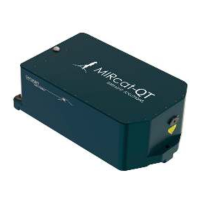
MIRcat laser head MIRcat laser head
Power cable Power cable for 110VAC, 60 Hz
Laser enable key Enable/disable laser power (key interlock)
Hose connectors (Qty 2) For water chiller connection (required for CW or high duty
cycle operation)
User Manual (on CD or USB
memory stick)
Contains: introduction and copies of user manual, GUI, and
SDK
To mount the MIRcat on an optical bench, you will need (not included):
Optical bench or table Metal optical bench to mount MIRcat laser head assembly.
3 hex head bolts,
2” (50mm) length
(¼-20 for English, or M6 for Metric).
Used for mounting MIRcat laser head to optical bench.
Hex (Allen) Key (3/16 for English, or M5 for Metric)
Used for mounting MIRcat laser head to optical bench.
3 Mount pedestals
(optional)
3 pedestal adaptors to raise beam height to desired height
Example: For a 4.5” beam height, use 0.5 inch (M6) New
Focus pedestals, #9910, with ¼-20 counterbore.
3 Pedestal clamping forks
(optional)
Used to clamp down the 3 pedestals above. Example: New
Focus 9909 (1 inch).
Tubing for connecting
liquid cooling
Clear vinyl tubing with 3/8” OD, and ¼” ID, (CW or high duty
cycle operation).
 Loading...