17
4.2 Water valve
The water valve supplies water to the reservoir for producing ice. The valve opens for one and a half minutes during initial start up
or power up of the unit and opens for two minutes at each harvest cycle after the drain valve has closed.
The valve has a built-in screen in the water supply tting. This screen will lter out any large particles and, over time, these par-
ticles will accumulate and restrict water supply. If this is found, simply clean the screen with a toothbrush to remove the particles.
DO NOT REMOVE THE SCREEN FROM THE VALVE.
To check the water valve:
Check the solenoid actuator for resistance. If no resistance is found, the valve will need to be replaced.1.
Check to see if the valve will seat properly. Foreign particles that may have passed the lter could damage the seat of the 2.
valve. To make sure the valve is seating, make sure power is disconnected to the unit, hook up the water supply, turn on the
water supply, and see if there is any water owing in the water lines. If water is present and owing, the valve will need to be
replaced.
Check the ow rate of the reservoir water line. Using a stopwatch or a watch with a second hand, see what amount of time it 3.
takes to ll up a one quart container. The time should be 60 seconds to get the 0.25 gpm specication of the valve.
If it takes substantially less than 60 seconds, check the water supply pressure to make certain it is not above 120 psi static •
pressure. If it is not, the metering orice of the valve has been damaged or changed and the valve will need to be replaced.
If it takes substantially more than 60 seconds, check the water supply pressure to make certain it is not below 20 psi static •
pressure. If it is not, make certain the valve screen lter is clean. If the lter is clean and pressure is above 20 psi, the valve is
defective and will need to be replaced.
Removing the Water Valve:
Disconnect power, water line, and drain line.1.
Remove the back panel and lower shroud (see Figure 3.3).2.
Remove the blue wire and white wire at the water valve terminals.3.
Loosen the reservoir water supply line compression nut from the bottom of the water valve.4.
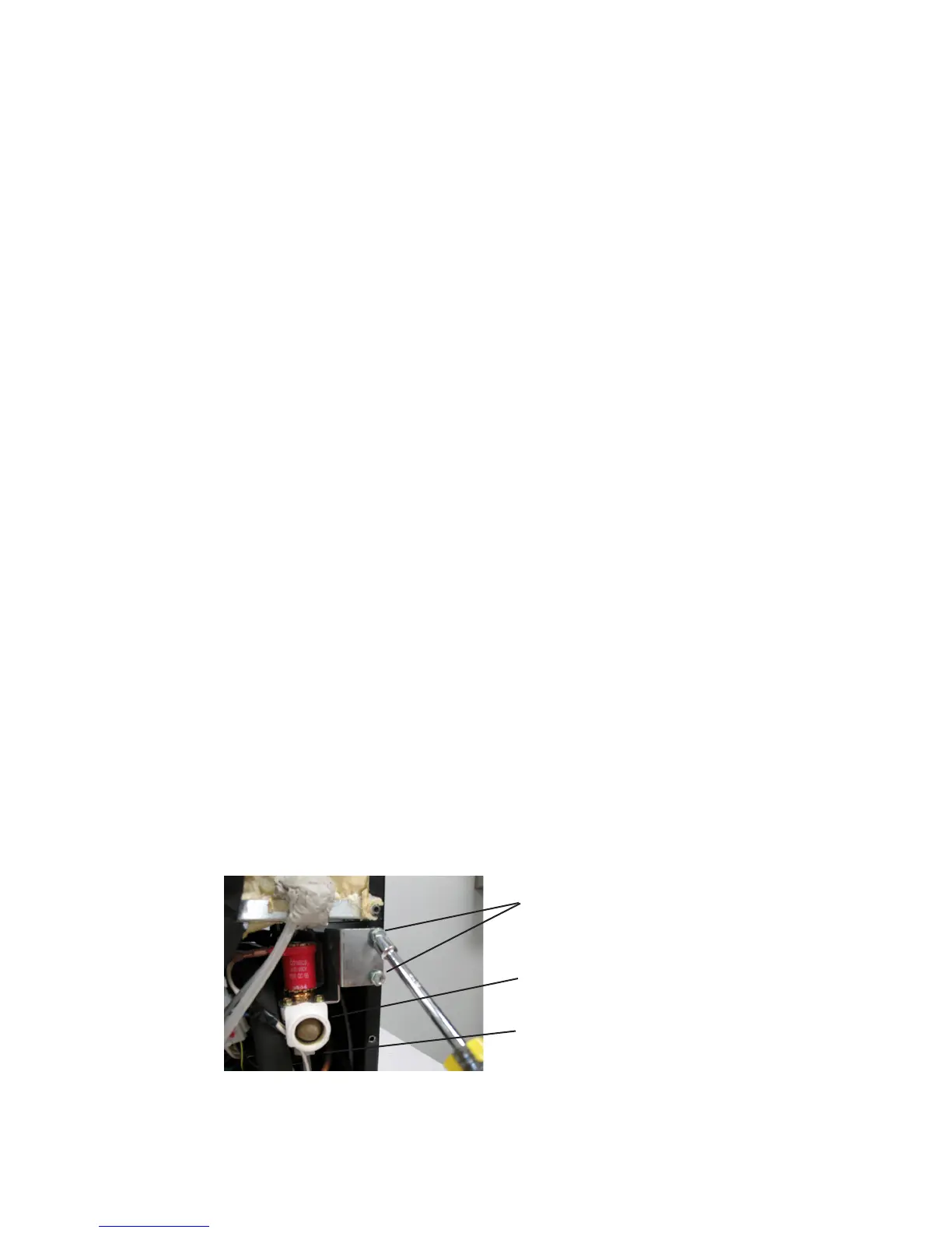
Remove the two screws securing the water valve to the ange of the cabinet (see Figure 4.3).5.
Remove the water valve.6.
Installing the Water Valve:
Reverse the removal procedure for installation (see above). Make certain that the reservoir water line is in the reservoir inside the
unit and there are no water leaks anywhere after installation.
Figure 4.3
Two screws that secure the water valve to the
cabinet ange.
Inlet water screen
Supply line compression nut
SEALED SYSTEM COMPONENTS