22
5.4 cUtter-griD tranSformer
The cutter-grid transformer is used to step down the voltage to the cutter-grid to 12VAC. The transformer is ON only from the
start of a harvest cycle to 35 minutes from the start of the production cycle. The transformer remains o at all other times. The
transformer itself can be checked by applying 120VAC to the marked 120V (for the hot lead) and COM (neutral lead) side of the
transformer and reading the 12V side using a multimeter.
If no readout is found or readout is below 10VAC, replace the transformer.
Removing the Transformer:
Disconnect power, water line, and drain line. If a drain pump is used, it will need to be disconnected and removed.1.
Remove the back panel and lower shroud (see Figure 3.3).2.
If a drain pump has been installed, it will need to be removed.3.
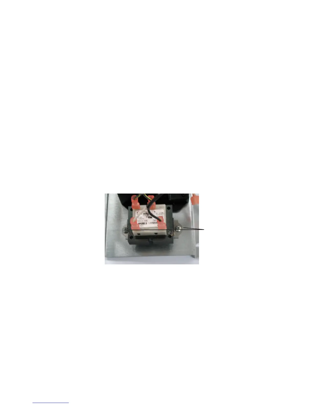
Remove the two Phillips head screws that secure the transformer to the electrical bracket (see Figure 5.4).4.
Mark and remove the four wires to the transformer.5.
Remove the transformer.6.
Installing the Transformer:
Reverse the removal procedure for installation (see above). Make certain all wire connections are secure and in the correct loca-
tion. Refer to the unit’s wiring diagram to verify (see Section 7, Wiring).
Figure 5.4
Transformer screws
SYSTEM COMPONENTS