22
Data Device Corporation
www.ddc-web.com
RDC-19220 SERIES
Q-05/05-0
ORDERING INFORMATION
RDC-19222_ -XXXX (Plastic Package: 44-pin J-Lead)
Supplemental Process Requirements:
T = Tape and Reel
Blank = None of the Above
Accuracy:
2 = 4 minutes + 1 LSB
3 = 2 minutes + 1 LSB
Process Requirements:
0 = No Burn-In
9 = Solder Dip, without Burn-In
Temperature Grade:
2 = -40 to +85°C
3 = 0 to +70°C
A = -40 to +125°C
Package Options:
Blank = Standard
G = Lead free
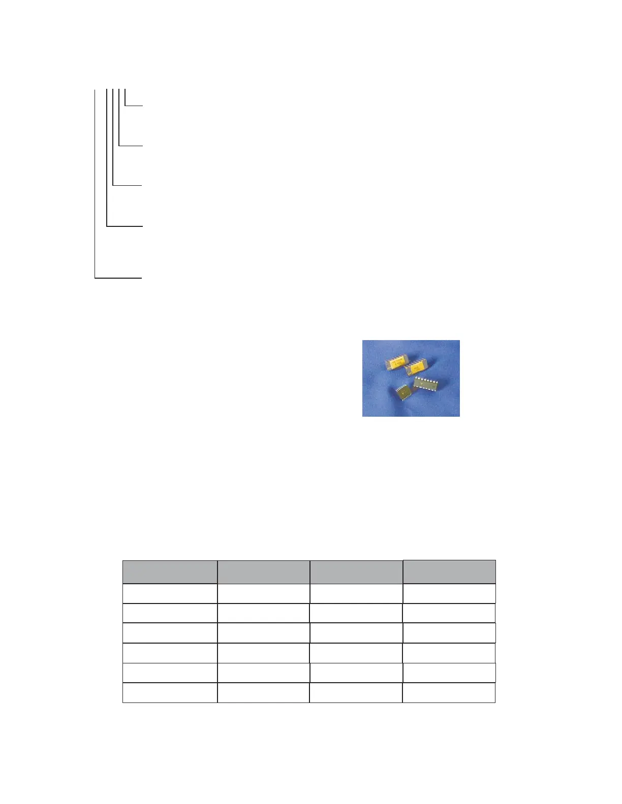
THIN FILM RESISTOR
NETWORK
DDC-55688-1
INPUT VOLTAGE
(VRMS)
OUTPUT VOLTAGE
(VRMS)
PACKAGE TYPE
2 Single Ended 2 Ceramic DIP
DDC-49530 11.8 2 Plastic DIP
DDC-57470 11.8 2 Surface Mount
DDC-49590 90 2 Ceramic DIP
DDC-73089 2 Differential 2 Surface Mount
DDC-57471
90 2 Surface Mount
Description
DDC converters such as the RDC-19220/2S and RD-19230 require closely matched 2Vrms
Sin/Cos input voltages to minimize digital error. DDC has custom thin film resistor networks
that provide the correctly matched 2Vrms converter outputs for 11.8Vrms Resolver/Synchro
or 90Vrms synchro applications.
Any imbalance of the resistance ratio between the Sin/Cos inputs will create errors in the
digital output. DDC’s custom thin film resistor networks have very low imbalance percent-
ages. The networks are matched to 0.02%, which equates to 1LSB of error for a 16-bit
application.
THIN FILM RESISTOR NETWORKS
FOR MOTION FEEDBACK PRODUCTS
Note: For thin film network specifications see the “Thin Film Network Specifications for Motion Feedback Products”
Data Sheet available from the DDC website.
(Operating Temperature Range : -55 to +125°C)
 Loading...