1) Resistors selected to limit Vref peak to between 1 V and 5 V.
needed, and -R is connected to GND.
3) See thin film network DDC-55688-1.
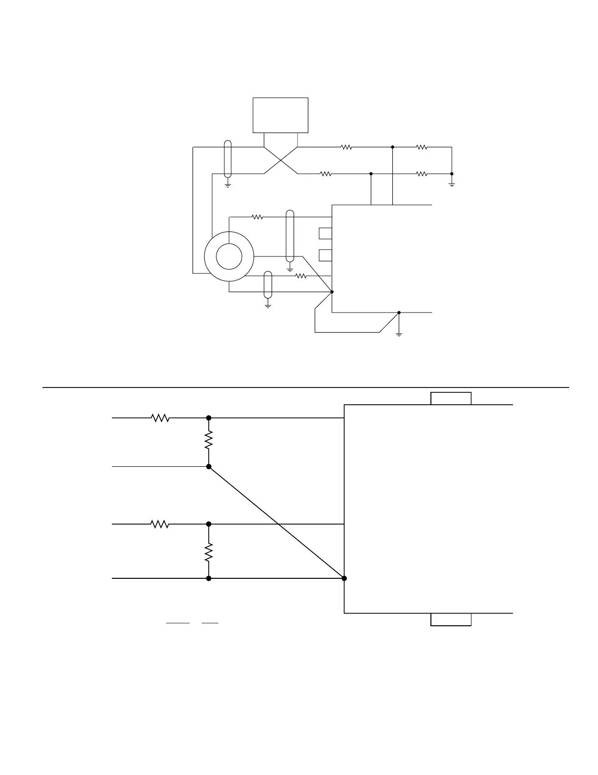
FIGURE 7A. TYPICAL CONNECTIONS, 2 V RESOLVER, DIRECT INPUT
FIGURE 7B. TYPICAL CONNECTIONS, X- VOLT RESOLVER, DIRECT INPUT
TYPICAL INPUT CONNECTIONS
FIGURES 7 through 9 illustrate typical input configurations
R2
=
2
R1 + R2 X Volt
R1 + R2 should not load the Resolver too much; it is recommended to use a R2 = 10k.
R1 + R2 Ratio Errors will result in Angular Errors,
2 cycle, 0.1% Ratio Error = 0.029° Peak Error.
Note: The five external BW components as
shown in FIGURE 1 and 2 are necessary
for the R/D to function.
Note: The five external BW components as
shown in FIGURE 1 and 2 are necessary for
the R/D to function.
 Loading...