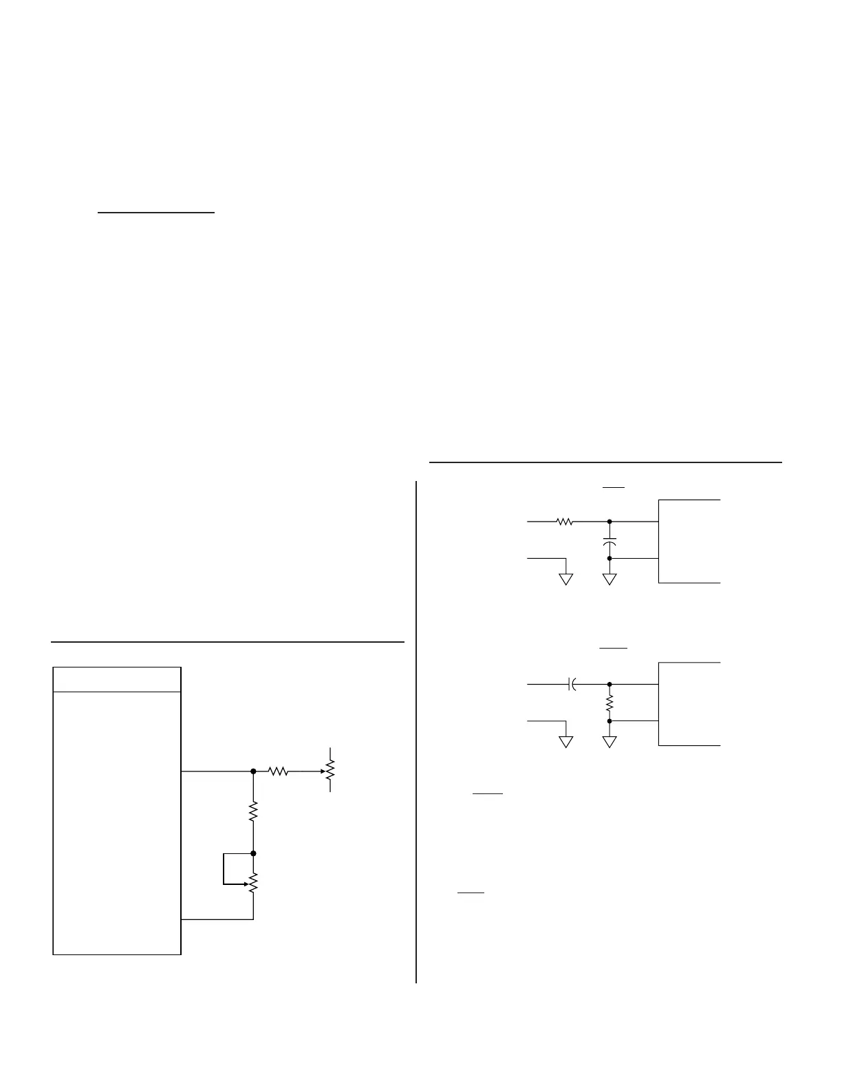
FIGURE 10. VELOCITY TRIMMING
FIGURE 11. PHASE-SHIFT COMPENSATION
X
c
tan ϕ =
R
Where ϕ = desired phase-shift
1
X
c
=
2π
fc
Where
f
= carrier frequency
Where
c
= capacitance
Calculate Rv for the maximum counting rate, at a VEL voltage
of 4 V.
For a 12-bit converter there are 2
12
or 4096 counts per rotation.
1,333,333/4096 = 325 rotations per second or 333,333 counts
per second per volt.
The maximum rate capability of the RDC-19220 is set by R
s.
When R
s = 30 kΩ it is nominally 1,333,333 counts/sec, which
equates to 325 rps (rotations per second). This is the absolute
maximum rate; it is recommended to only run at <90% of this rate
(as seen in TABLE 3), therefore the minimum R
v
will be limited
to 55 kΩ. The converter maximum tracking rate can be increased
50% in the 16- and 14-bit modes and 100% in the 12- and 10-bit
modes by increasing the supply current from 12 to 15 mA (by
using an R
c = 23 kΩ), and by increasing the sampling rate by
changing R
s to 20 kΩ for 16- and 14-bit resolution or to 15 kΩ for
12- and 10-bit resolution (see TABLE 4).
The maximum carrier frequency can, in the same way, increase
from: 5 to 10 kHz in the 16-bit mode, 7 to 14 kHz in the 14-bit
mode, 11 to 32 kHz in the 12-bit mode, and 20 to 40 kHz in the
10-bit mode (see TABLE 5).
The maximum tracking rate and carrier frequency for full perfor-
mance are set by the power supply current control resistor (R
c)
per the following tables:
The carrier frequency should be 1/10, or less, of the sampling fre-
quency in order to have many samples per carrier cycle. The con-
verter will work with reduced quadrature rejection at a carrier fre-
quency up to 1/4 the sampling frequency. Carrier frequency should
be at least 3.5 times the BW in order to eliminate the chance of jitter.
REDUCED POWER SUPPLY CURRENTS
When Rs
= 30 kΩ (tracking rate is not being pushed), nominal power
supply current can be cut from 14 to 9 mA by setting R
c = 53 kΩ.
TRANSFORMER ISOLATION
System requirements often include electrical isolation. There are
transformers available for reference and synchro/resolver signal
isolation. TABLE 6 includes a listing of the most common trans-
formers.The synchro/resolver transformers reduce the voltage to
2 Vrms for a direct connection to the converter. See FIGURES
5A, 5B, 5C and 5D for transformer layouts and schematics, and
FIGURE 6 for typical connections.
DC INPUTS
As noted in TABLE 1, the RD-19220/2 will accept DC inputs.
 Loading...