Ri
x 2 Vrms = Synchro L-L rms voltage
Rf
Rf ≥ 6 kΩ
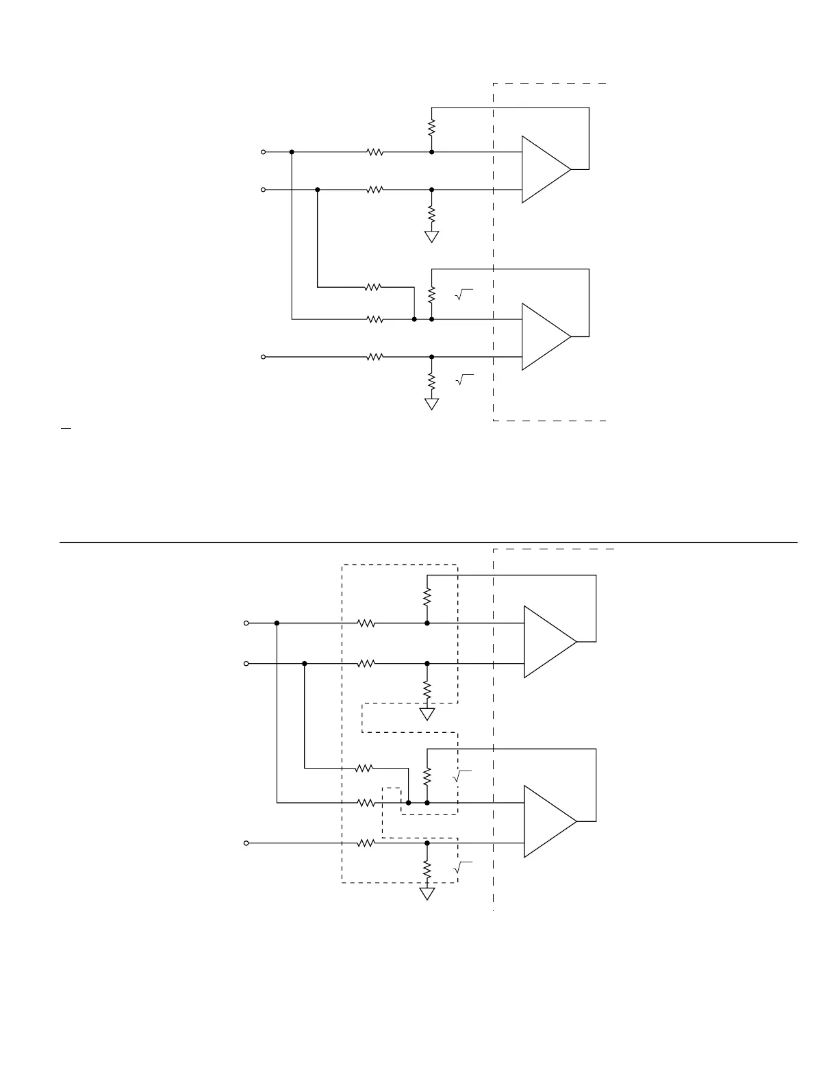
S1, S2, and S3 should be triple twisted shielded; RH and RL should be twisted shielded, In both cases the shield should be tied to GND at the
converter.
FIGURE 9A. SYNCHRO INPUT
FIGURE 9B. SYNCHRO INPUT, USING DDC-49530/DDC-57470 (11.8 V), DDC-73089 (2V) OR DDC-49590 (90 V)
S1, S2, and S3 should be triple twisted shielded; RH and RL should be twisted shielded, In both cases the shield should be tied to GND at the converter.
90 V input = DDC-49590: Ri = 270 kΩ, 90 V input, synchro or resolver.
11.8 V input = DDC-49530 or DDC-57470: Ri = 70.8 kΩ, 11.8 V input, synchro or resolver.
Maximum addition error is 1 minute.
Note: The five external BW components as
shown in FIGURE 1 and 2 are necessary
for the R/D to function.
Note: The five external BW components as
shown in FIGURE 1 and 2 are necessary
for the R/D to function.
 Loading...