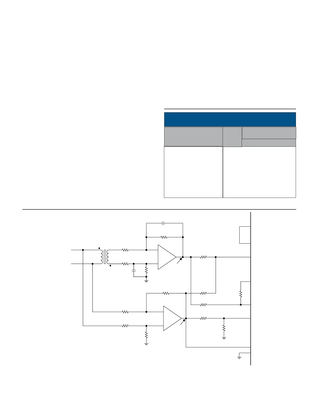
FIGURE 12A. 2-WIRE LVDT DIRECT INPUT
TABLE 7. LVDT OUTPUT CODE (14-BIT R/D OR
12-BIT LVDT)
DATA
+ over full travel
+ full travel -1 LSB
+0.5 travel
+1 LSB
null
- 1 LSB
-0.5 travel
- full travel
- over full travel
01 xxxx xxxx xxxx
00 1111 1111 1111
00 1100 0000 0000
00 1000 0000 0001
00 1000 0000 0000
00 0111 1111 1111
00 0100 0000 0000
00 0000 0000 0000
11 xxxx xxxx xxxx
C
1
= C
2
, set for phase lag = phase lead through the LVDT.
Note: TABLE 7 refers to FIGURE 12C.
• Operation from 0° to 180° or 180° to 359° only. This is due to
the possibility of a unstable false null. IE: 180° hang-up. This 180°
hang-up is unstable and once the converter moves it will go to
the correct answer. In real world applications where an instanta-
neous 180° change are not possible the converter will always be
correct within 360°. The problem arises at power-up in real sys-
tems. If the converter angle powers up at exactly 180° from the
applied input the converter will not move. This is very unlikely
although it is theoretically possible. This condition is most often
encountered during wrap around verification tests, simulations or
troubleshooting.
• Set the REF input to DC by tying RH to +5V and RL to GND or
-5V.
• Set the COS and SIN inputs such that max signal will be equal
to 1.8VDC. IE: For 90°, the SIN input will equal 1.8VDC. This will
keep the BW hysteresis consistant with AC operation.
• Input offsets will affect accuracy. Verify the COS and SIN inputs
do not have DC offsets. If offsets are present , a differential op
amp configuration can be used to minimize differential offset
problems.
• With DC inputs the converter BIT will remain at logic 0.
• The Bandwidth value of the converter should be chosen based
on the rate of change of the system’s input amplitude variation,
and should be large enough so to minimize it’s effect on the sys-
tem dynamics. Note that if the bandwidth is too high the system
will be more susceptible to noise.
• The accuracy of the converter using a DC input will be degrad-
ed from the rated accuracy. Consider the best case where the
input is single ended and no additional DC offsets are present on
the input converter - the accuracy will degrade by about 2 arc
minutes. IE:, If a part is rated at 2 arc minutes, a DC input will
degrade the accuracy to approximately 4 arc minutes.
LVDT OUTPUT
MSB LSB
OVER
RANGE
 Loading...