14
Data Device Corporation
www.ddc-web.com
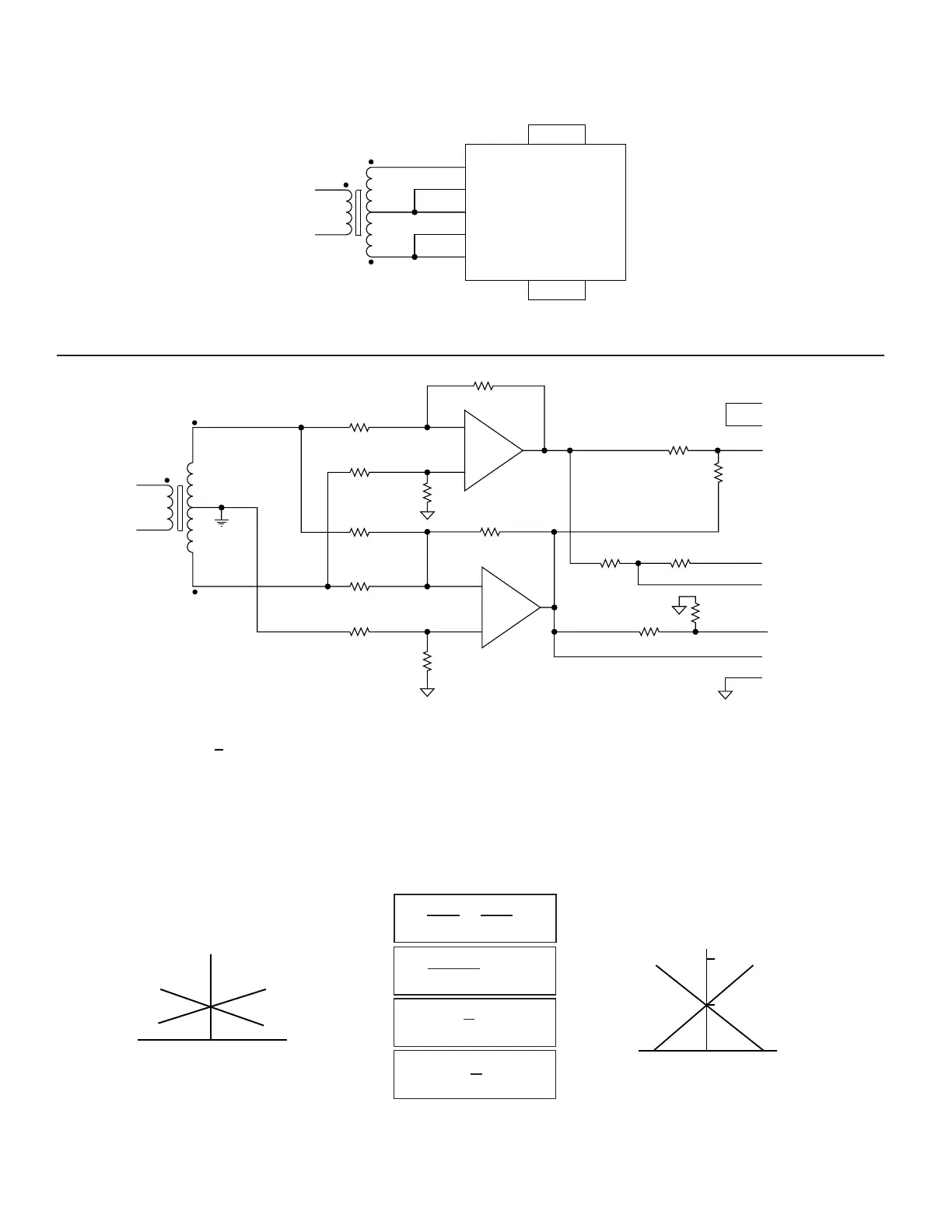
RDC-19220 SERIES
Q-05/05-0
+S
-S SIN
-C COS
-REF
+REF
A GND
+C
RDC-19220
+S
-S
SIN
aR
R
+C
-C
COS
R'
-
+
-
+
R/2
R
R
aR
bR
2R'
2R'
R'
bR
+REF
-REF
R'
R'
R
V
B
V
A
REF
-2V
FS=2V
Notes:
1. R' > 10kΩ
2. Consideration for the value of R is LVDT loading.
3. RMS values given.
4. Use the absolute values of Va and Vb when subtracting per the formula for
calculating resistance values, and then use the calculated sign of "Va and Vb"
for calculating SIN and COS. The calculations shown are based upon full scale
travel being to the Va side of the LVDT.
5. See the RDC application manual for calculation examples.
6. Negative voltages are 180˚ phase from the reference
V
B
V
A
LVDT
OUTPUT
+FS -FSNULL
COS
SIN
RDC-19220
INPUT
-FS +FSNULL
1V
2V
FIGURE 12B. 3-WIRE LVDT DIRECT INPUT
FIGURE 12C. 3-WIRE LVDT SCALING CIRCUIT
1
V
b = =
Anull
1
V
Bnull
2
(V - V )
a =
AB
SIN=-1V+ (V - V )
AB
a
2
COS=-1V - (V - V )
AB
a
2
max.
 Loading...