the data bus.
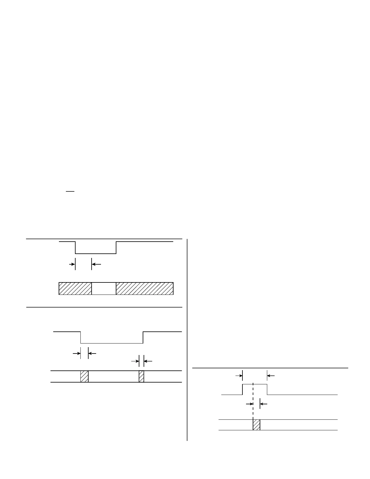
FIGURE 13. INHIBIT TIMING
FIGURE 14. ENABLE TIMING
FIGURE 15. CONVERTER BUSY TIMING
VELOCITY TRIMMING
RDC-19220 Series specifications for velocity scaling, reversal
error and offset are contained in TABLE 1. Velocity scaling and
offset are externally trimmable for applications requiring tighter
specifications than those available from the standard unit. FIG-
URE 10 shows the setup for trimming these parameters with
external pots. It should also be noted that when the resolution is
changed, VEL scaling is also changed. Since the VEL output is
from an integrator with capacitor feedback, the VEL voltage can-
not change instantaneously. Therefore, when changing resolu-
tion while moving there will be a transient with a magnitude pro-
portional to the velocity and a duration determined by the con-
verter bandwidth.
INCREASED TRACKING/DECREASED SETTLING
(GEAR SHIFTING)
Connecting the BIT
output to the resolution control lines (A and
B) will change the resolution of the converter down (“gear shift”)
and make the converter settle faster and track at higher rates.
The converter bandwidth is independent of the resolution.
ADDITIONAL ERROR SOURCES
Quadrature voltages in a resolver or synchro are by definition the
resulting 90° fundamental signal in the nulled out error voltage (e)
in the converter. This voltage is due to capacitive or inductive cou-
pling in the synchro or resolver signals. A digital position error will
result due to the interaction of this quadrature voltage and a refer-
ence phase shift between the converter signal and reference
inputs. The magnitude of this error is given in the following formula:
Magnitude of Error = (Quadrature Voltage/F.S.signal) • tan α
Where:
Magnitude of Error is in radians
Quadrature Voltage is in volts
Full Scale signal is in volts
α = signal to REF phase shift
An example of the magnitude of error is as follows:
Let: Quadrature Voltage = 11.8 mV
Let: F.S. signal = 11.8 V
Let: α = 6°
Then: Magnitude of Error = 0.36 min @ 1 LSB in the 16th bit.
Note: Quadrature is composed of static quadrature which is
specified by the synchro or resolver supplier plus the speed
voltage which is determined by the following formula:
Speed Voltage = (rotational speed/carrier frequency) • F.S. signal
Where:
Speed Voltage is the quadrature due to rotation.
Rotation speed is the rps (rotations per second) of the synchro
or resolver.
Carrier frequency is the REF in Hz.
PHASE SHIFT COMPENSATION
FIGURE 11 illustrates a circuit to LEAD or LAG the reference
into the converter that will compensate for phase-shift between
the signal and the reference to reduce the effects of the quadra-
ture. This should be used for greater than 6° phase shift between
Ref and COS/SIN inputs.
 Loading...