EN-4
4 ELECTRICAL CONNECTIONS
Execute the wiring following the directions of “Table 1” and diagrams on page I-1.
WARNING To ensure an appropriate level of electrical safety always keep the 400V 3~ power supply cables apart (minimum 4mm in the
open or 1 mm through insulation) from low voltage cables (motors power supply, controls, aerial and auxiliary circuits power supply),
taking care to place them in plastics ducts and fasten the latter with appropriate clamps near the terminal boards.
WARNING For connection to the mains, use a multipolar cable having a minimum section 3x1,5 mm² and complying with the current
regulations. For connecting the motors, use a minimum cross section 1,5 mm² cable and complying with the current regulations. As
an example, if the cable is out side (outdoor), must be at least equal to H07RN-F, whereas if it (in a raceway), must be at least equal to
H05VV-F.
WARNING All cables must be stripped in the immediate nearbys of the terminals. Keep cables slightly longer in order to eliminate
subsequently any excess.
WARNING In case of operators provided with electromechanical brake, remind to deactivate the elecrtonic brake of the control board
(P029=0).
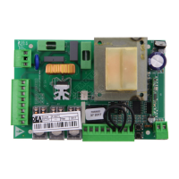
Table 1 “terminal board connections”
1-2-3 Three-phase power supply connection: Connect the three phases to clamps 1, 2 and 3
4-5-6 Three-phase motor output: 4=phase T1, 5=phase T2, 6=phase T3 (max 1200W)
7-8 Flashing light output 230V ~ max 75mA
9-10
Clean Contact with max capacity 5A: this contact may be used to command a opened gate warning light (P027=0), or a
courtesy light (P027≠0), or to pilot an eventual mechanical brake (P029=2). In case of mechanical brake, opened gate
warning light and courtesy light are deactivated independently from the value assigned to P027.
11-12
24V ~ Power supply output for controlled safety devices. To be used as power supply for photocell transmitters (in all cases)
and of safety devices when testing these latter before each gate operation.
11-13
24V ~ Power supply output for auxiliary circuits and uncontrolled safety devices. To be used as power supply for any auxiliary
devices, photocell receivers (in all cases) and of safety devices when testing these latter before each gate operation.
14-15 12V ~ max 15VA Electric lock output
16 Common inputs
17
N.C. external safety device input. In case of activation, it reverses the movement (P018=0) or it stops (P018=1). If unused,
short-circuit to terminal n°16 or n°24
18 N.C. input Limit switch in opening. If unused, short-circuit to terminal n°16 or n°24
19 N.C. input Limit switch in closing. If unused, short-circuit to terminal n°16 or n°24
20
N.O. Pedestrian opening button input. If activated, it partially opens the gate (P030>3); Separate lock (P030=1); Man
present command (P030=2); separated/CLOSE present man command (P030=3); centralized closing (P030=0)
21
N.C. Photocell input. In case of activation it reverses the movement only while closing (P026=0) or it reverses the movement
while closing and stops while opening (P026=1). If unused short-circuit to terminal n°16 or n°24.
22 N.C. Stop input. If activated, it stops the movement during any operation, if unused, short-circuit to terminal n°16 or n°24
23 N.O. Start input. If activated it opens or closes the gate. It can work in “reversal” mode (P025=0) or “step by step” (P025=1)
24 Common inputs
25 Radio antenna signal input
26 Radio antenna earth input
 Loading...