Caution!!! For model AAB-500.1D the operating voltage is 9-15 V.
5
EN
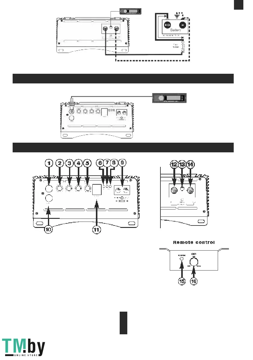
3. LPF – low pass filter (35 Hz – 80 kHz at 12 dB/Oct)
9. SPEAKER OUTPUT – speaker terminal connections
1. INPUT – signal input, RCA jack
2. SUBSONIC – subsonic frequency filter (15 Hz – 50 Hz at 12 dB/Oct)
4. GAIN – input signal level adjustment (0.2 – 6 V)
5. BASS BOOST – bass level adjustment 0 – 12 dB
6. POWER – LED for operation (blue)
7. CLIP – LED on the clip (yellow)
8. PROTECT – LED for operation (red)
11. REMOTE - input for connection of the bass remote control
12. +12V – power supply terminal (+12V)
13. REM IN – connector of remote activation of the amplifier
14. GND – grounding supply terminal «-»
15. POWER – LED for operation (blue)
16. GAIN – input signal level adjustment
10. OUTPUT - signal output, RCA jack
Appl i catio n of conne ct o rs a n d co ntro ls
Step 1. Connect one end of the RCA cable to the RCA output terminals at the HU and the second end to the amplifier RCA input
terminal marked with INPUT.
St an d ard w i ri n g di agr am o f m on o a mp lif ier t o He a d Un i t.
 Loading...