6
2+2 Ohm
4+4 Ohm
8 Ohm
4 Ohm
1+1 Ohm
2 Ohm
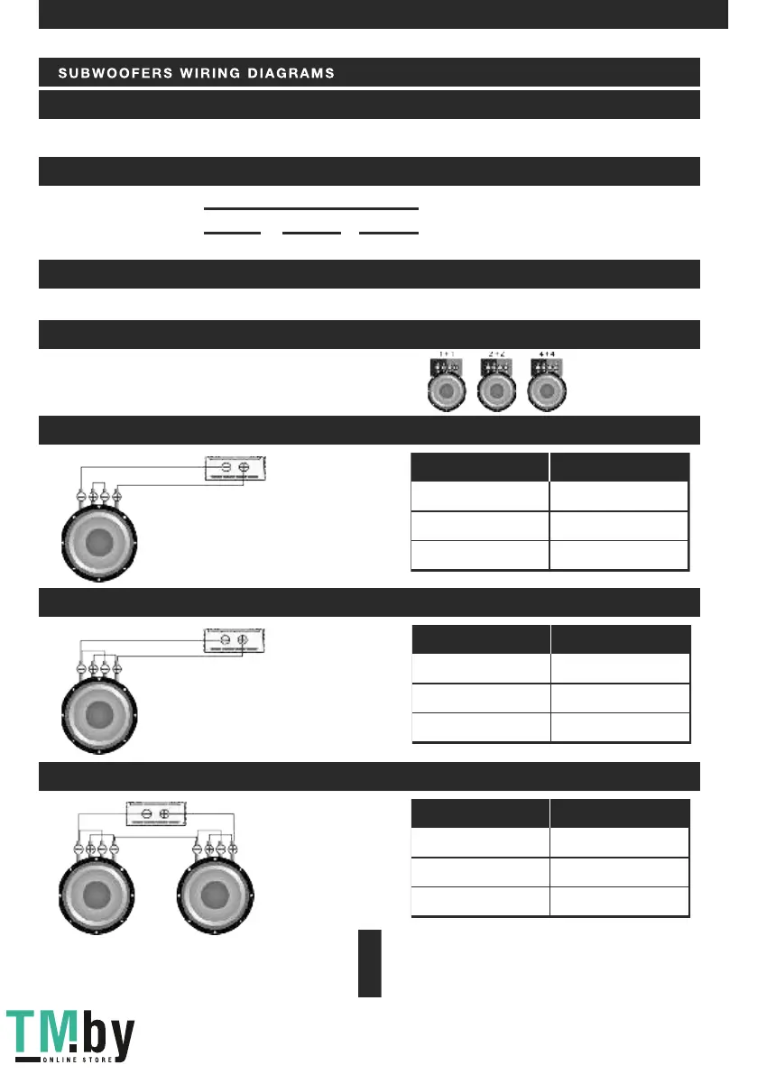
On e su b wo o fe r, co i ls i n s er ies
On e su b wo o fe r, co i ls i n p ar all el
Voice coils
Total impedance
Su bw o of e rs i n ser ie s , co i ls i n par al l el
2+2 Ohm
4+4 Ohm
2 Ohm
1 Ohm
1+1 Ohm
0.5 Ohm
Voice coils
Total impedance
2+2 Ohm
4+4 Ohm
4 Ohm
2 Ohm
1+1 Ohm
1 Ohm
Voice coils
Total impedance
Se ri a l co n ne cti on
Pa ra l le l c on nec ti o n
SC HE M ES O F E NA BLI NG T H E LO A D OF T HE SU BWO OF E R
Voi ce c o il s 1 +1 , 2+2 , 4+ 4 O hm
Tot a l im p ed a nc e = Ω Su b 1 + Ω S u b 2 + Ω S u b 3 .. .
Ω Sub 1 + Ω Sub 2 + Ω S u b 3 . . .
Tot a l im p ed a nc e =
1
1
1
1
...
...
The minimum permissible load impedance at the output of the amplifier is 1 ohm. Use these formulas to calculate the
load impedance of various types of connections.
6. CONNE C T I O N METHOD S
The subwoofer has voice coil D1, D2 or D4.
In any case do not expose the amplifier to the loads lower than specified by the manufacturer. Use these schematics to
calculate load impedance of different connection types.
EN