4.4.2
4.4.1
9
1 3 4 5 6 7 8
2
4.4.2
4.4.3
3
4
5
8
7
of
INDUSTRIAL PUMPS
www.debem.com
rev
4.4 PNEUMATIC CONNECTION
The connection operations to the pneumatic system are reserved for qualied and authorised Installers,
equipped with suitable Personal Protective Equipment (PPE), who know and comply with the contents of
this Manual. After completing the installation, it is possible to connect the pump to the pneumatic supply
circuit as follows:
Pneumatic system requirements
• Supply with non-lubricated, dried air, with suitable pressure (Min 2 bar - Max 8 bar);
• Use of pneumatic components with air ow rates suitable for the pneumatic circuit of the pump;
• Glycol adder for installations with strong delivery heads and/or back-pressures;
• Installation of an on-off valve, 3-way valve and check valve on the air supply;
• Installation of an air discharge pipe (with collection) outside environments with a heavy and potentially
explosive atmosphere and for pumping ammable or toxic uids.
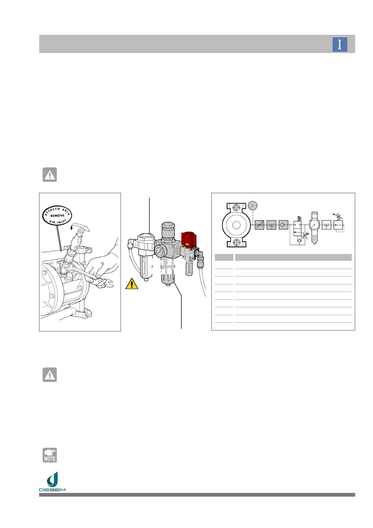
Remove the adhesive sticker from the air connection of the pump.
CAUTION: danger of pump blocking.
BOXER pumps must be pneumatically fed using NON-LUBRICATED, FILTERED AND DRIED com-
pressed air at a pressure of no less than 2 bars and not more than 8 bars.
POS. COMPONENT
1 Air pump
2 Pressure gauge
3 Adjustment valve (SPEED)
4 3-way valve - air discharge (START - STOP)
5 Check valve
6 Soft start valve
7 Filter/Regulator (20µ - micron)
8 3-way valve - interlockable (EMERGENCY)
9 Pressure Relief Valve
Tighten a compressed air ow control valve, a 3-way valve (START - STOP with air discharge) and a check valve on
the pneumatic circuit connection of the pump, as per the diagram in the gure. Install a pressure gauge
on the compressed air connection of the pump itself and check the value with the pump running to check
the real pressure of the supply air.
CAUTION: danger of uid entering the compressed air circuit and being discharged into the environment.
Do not install the pump without the 3-way valve (START - STOP) and/or the check valve to prevent the pumped
uid from entering the pneumatic circuit if the diaphragms break.
Even in battery installations, the check valve must always be installed on each pump.
Install a 3-way EMERGENCY stop valve upstream of the pneumatic supply circuit (disconnector with interlock) in a
protected and easily accessible position.
Installations where operation with many Start / Stop cycles is expected (with high delivery heads and / or with
strong back-pressures) require the installation of a pneumatic soft start valve to protect the product dia-
phragms.
NOTE
The installation of the soft start pneumatic valve, in addition to allowing a more uniform and uid pump-
ing of the product during the start-up phase, allows the protection of the diaphragms and preserves the
operating life of the pump.
NO
OIL
ONLY
Air Filter
Min 2 bar
Max 8 bar
ONLY
for glycol


 To Next Page