E – Mechanical Installation
April, 2018 E-10 INM.XX.X.00
“Split-Cut” dehumidifier – mechanical field assembly
Under special conditions, the dehumidifier may be split into two or more sections to ease the installation and
delivery process. Refer to the dehumidifier submittal drawings and Disassembly and Assembly Instructions,
provided with the dehumidifier (instructions include mechanical, piping, and electrical guidance for reassembly).
Place and align dehumidifier sections properly:
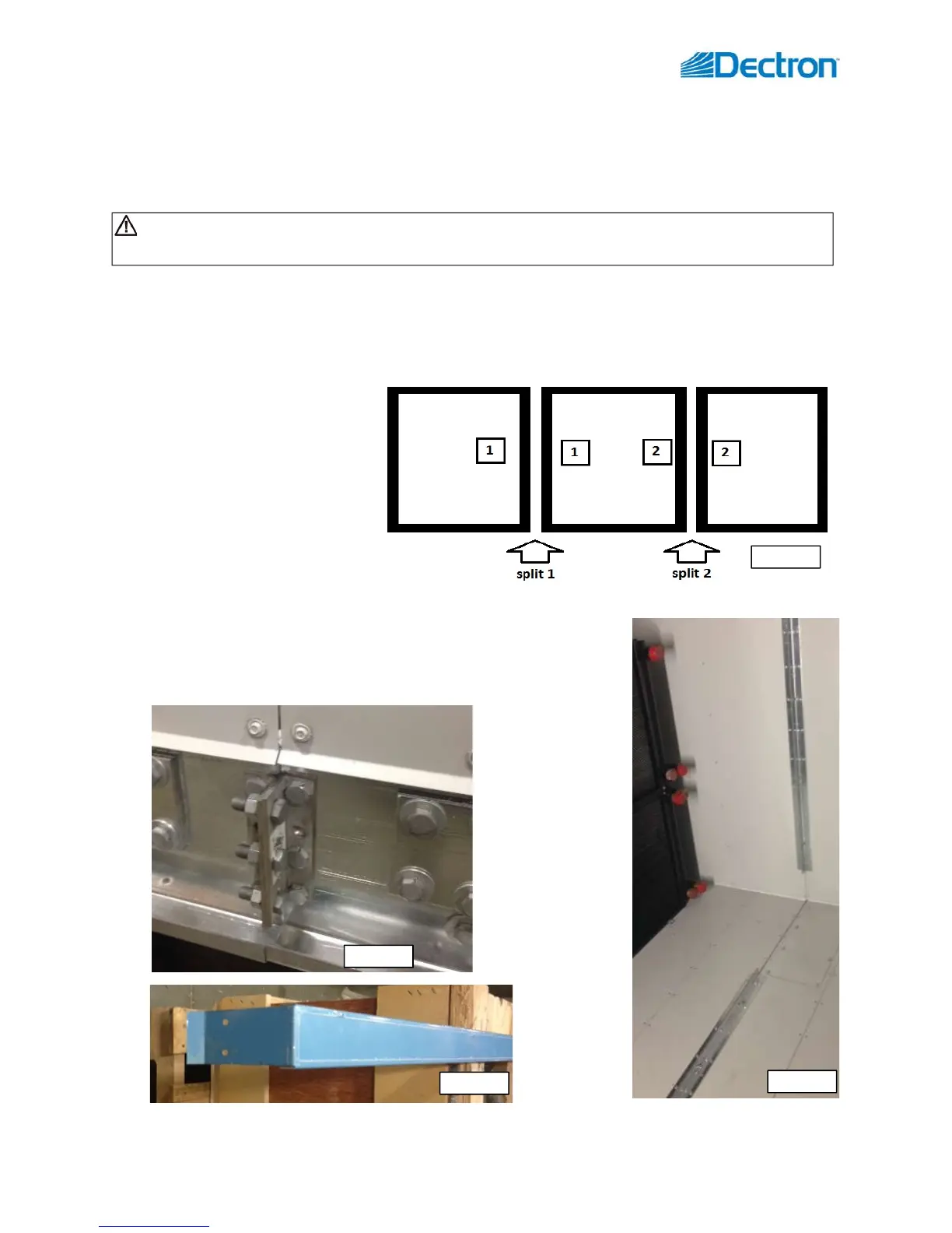
o To aid with proper placement, sections normally are labeled with sequential numbers (“1”, “2” etc.) –
ensure that each pair of adjacent sections at the split have same number (see Pic. E.10a).
o Before final assembly of sections – ensure piping proper alignment; plan for pipe joining.
Join sections with provided fasteners.
o Base angles (outside – see
Pic. E.10. b) are normally
bolted together with 3/8”
bolts and internal (walls,
floor, ceiling) angle (inside
– see Pic. E.10 c) are
normally attached with
5/16” bolts.
o Internal angles shape may
vary depending on
dehumidifier cabinet type.
o Ensure that all provided holes are used.
Install provided roof rib cap (see Pic. E.10 d) over each jointed roof rib and
attach it with screws; caulk the inner corner of roof rib cap prior.
Caulk all the joints (roof, floor, walls) after reassembly.
WARNING! DO NOT lift assembled dehumidifier. Lift each section separately and assemble once all
sections are placed where intended.
Pic.E.10a
Pic.E.10c
Pic.E.10b
Pic.E.10d