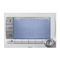
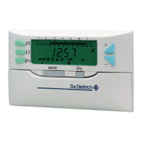
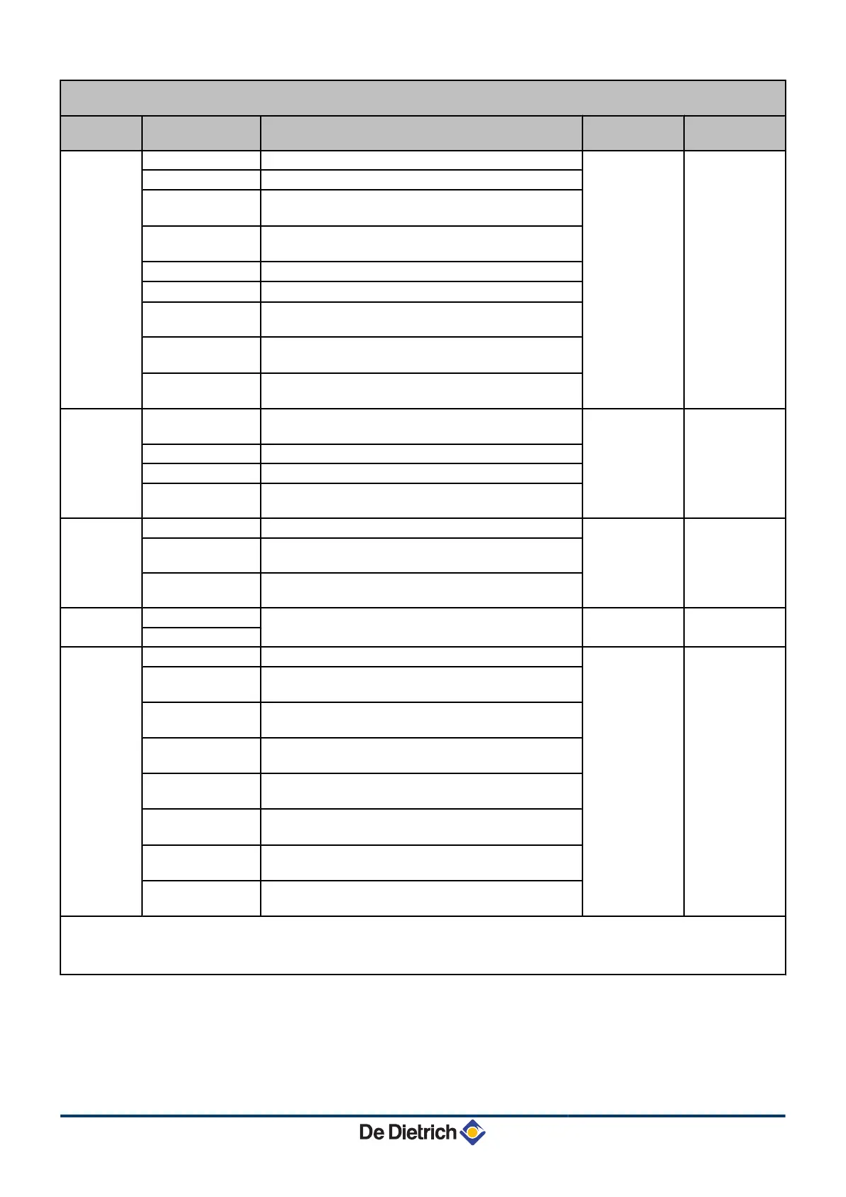
Installer level - #SYSTEM menu
Parameter Adjustment range Description Factory setting Customer
setting
S.AUX
(1)(4)
DHW LOOP
Use as a domestic loop pump
DHW LOOP
PROGRAM.
Use as an independent programmable outlet
PRIMARY PUMP
The outlet MAUX is active if a heating demand is
present on the secondary pump
ORDER BURNER
The outlet MAUX is active when a burner demand is
present
DHW
Use of primary circuit of second DHW tank
FAILURE
The outlet MAUX is active if an fault is detected
DHW ELEC
Used to control the electrical resistor according to the
timer programme on circuit AUX in summer mode
DEF.CASC
Output MAUX is active if a default is present in one of
the boilers in the cascade
VM P
Output MAUX is active if at least one circuit of the
connected VM is in demand
I.SYST
(1)
SYSTEM
The inlet sensor is used to connect the common flow
sensor of a cascade system
SYSTEM
BUFFER TANK
Hot water storage tank affected to heating only
DHW STRAT
Using the DHW tank with 2 sensors (top and bottom)
ST.TANK+DHW
Hot water storage tank affected to heating and domestic
hot water
O.TEL
(1)
FAILURE
The telephone outlet is closed in the event of failure
FAILURE
REVISION
The telephone outlet is closed in the event of revision
display
DEF+REV
The telephone outlet is closed in the event of failure or
revision display
CT.TEL
(1)
CLOSE
See table hereafter.
CLOSE
Open
I.TEL
(1)
ANTIFR
Boiler anti-freeze activation
ANTIFR
0/1 A
ON or OFF contact: I.TEL can be used as an antifreeze
activation inlet on circuit A
0/1 B
ON or OFF contact: I.TEL can be used as an antifreeze
activation inlet on circuit B
0/1 A+B
ON or OFF contact: I.TEL: can be used as an antifreeze
activation inlet on circuits A+B
0/1 C
ON or OFF contact: I.TEL can be used as an antifreeze
activation inlet on circuit C
0/1 A+C
ON or OFF contact: I.TEL: can be used as an antifreeze
activation inlet on circuits A+C
0/1 B+C
ON or OFF contact: I.TEL: can be used as an antifreeze
activation inlet on circuits B+C
0/1 A+B+C
ON or OFF contact: I.TEL: can be used as an antifreeze
activation inlet on circuits A+B+C
(1) The parameter is only displayed if INSTALLATION is set to EXTENDED
(2) If the pump incorporated in the boiler is used for circuit A (parameter CIRC.A set to DIRECT), the MA outlet is free
(3) This setting cannot be modified
(4) The parameter is only displayed if the parameter O.PUMP A is set to CIRC.AUX or if the 3-way valve PCB option is connected
5. Commissioning Diematic iSystem For C 330 / C 630 ECO
35
31082018 - 7600691-001-06
 Loading...