To plant supply +ve
Crank
Starter
motor
Battery
Charge
alt.
WL
F F
Fuel
Emergency
stop
internal emergency stop
Configurable auxiliary input 1
Configurable auxiliary input 2
Configurable auxiliary input 3
Configurable auxiliary input 4
Configurable auxiliary input 5
L1
L2
L3
N
F2A F2A F2A
+
Supply for
controller
These ground connections must be
on the engine block and must be
a sound electrical connection
to the sender bodies.
The ground wire to terminal 47 must
not be used to provide a ground
connection to any other device.
Coolant temp. sender
Fuel level sender
RS485
Optional
9 way D
Optional
RS232
5220 controller
Optional
CanBus
Not connected
Output expansion
157 relay board
or
548 annunciator
5200 series
configuration software
810 interface
810
157/548
Ground screen
at one end only
Functional
Earth
MPU
17
18
16
6 7 8
1413
12
1110
474645
Oil pressure sender
449
4
531 2
39 40 41 42
43
CT
common
CT
Earth
35
36 37 38
20 21 22
23
24
25
26
Configurable auxiliary input 6
15
Configurable auxiliary output 1
Configurable auxiliary output 2
Configurable auxiliary output 3
SCR A
B
COM H
L
Not connected
F2A F2A F2A
31
32 33 34
G M
LOAD
Mechanical interlock
Electrical interlock
Generator Mains (utility)
19
Not connected
28273029
Generator
loading
relay
Mains
loading
relay
L1
L2
L3
N
Dimensions
Module Dimensions - 240mm x 172mm x 57mm (9.45” x 6.77” x 2¼”)
Panel cutout - 220mm x 160mm ( 8.7” x 6.3”)
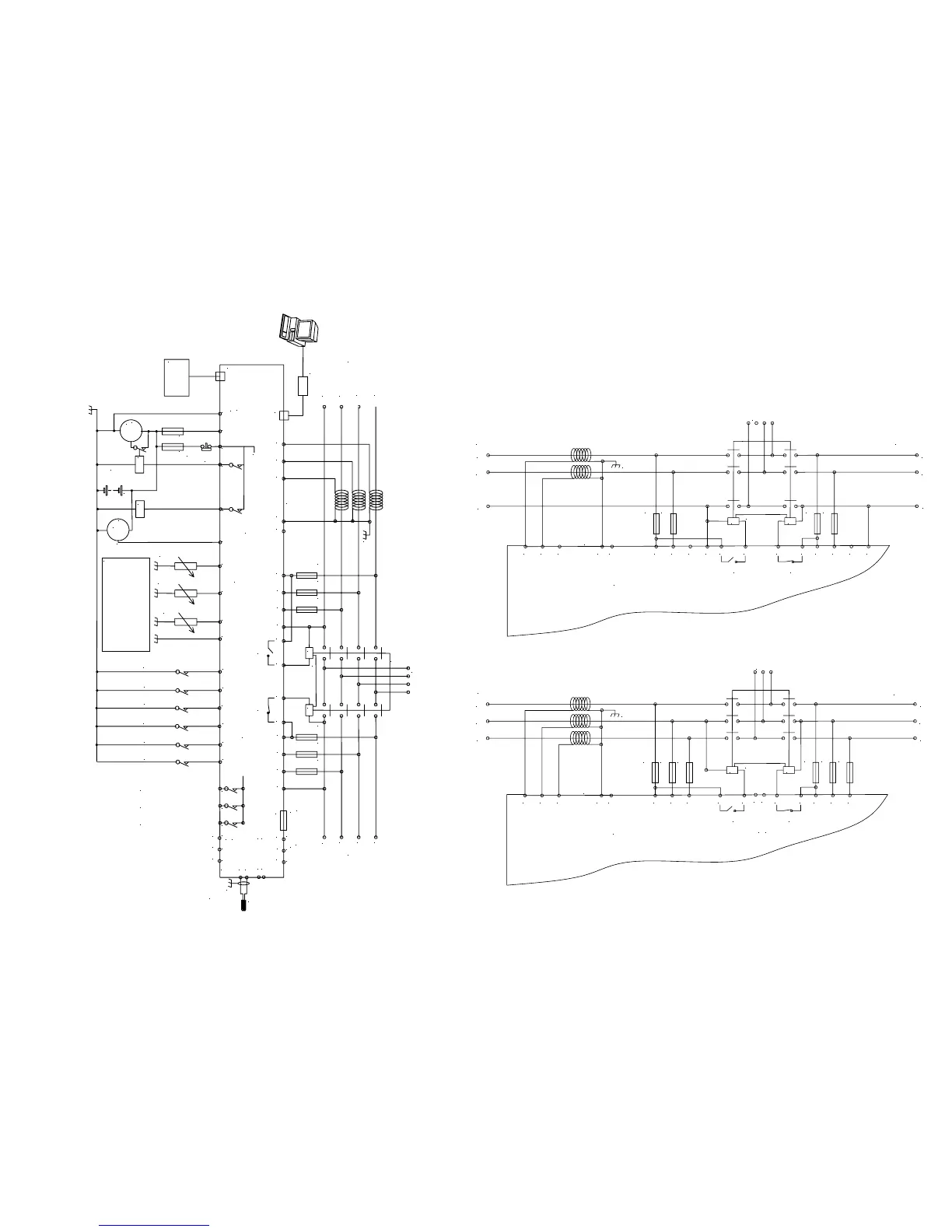
Alternative AC wiring
2 phase, 3 wire ( 2 phase centre tap neutral)
L1
L2
N
F2A F2A
39 40 41 42 43
CT
common
CT
Earth
35
36 37 38
Not connected
F2A F2A
31
32 33 34
G M
LOAD
Mechanical interlock
Electrical interlock
Generator Mains (utility)
28273029
Generator
loading
relay
Mains
loading
relay
L1
L2
N
3 phase, 3 wire
L1
L2
L3
F2A F2A F2A
39 40 41 42
43
CT
common
CT
Earth
35 36 37
38
Not connected
F2A F2A F2A
31
32 33
34
G M
LOAD
Mechanical interlock
Electrical interlock
Generator
Mains (utility)
28273029
Generator
loading
relay
Mains
loading
relay
L1
L2
L3
Not connected
Not connected
T
 Loading...