Do you have a question about the DEEP SEA ELECTRONICS DSEGenset DSE6120 MKIII and is the answer not in the manual?
Explains notation and symbols used throughout the manual for clarity.
Provides definitions for technical terms used in the operator manual.
Lists DSE publications and third-party documents referenced in the manual.
Lists training guides covering specific subjects related to DSE products.
Specifies the operating temperature range for the DSE61XX MKIII module.
Specifies the operating temperature range for the DSE61XX MKIII module.
Details specifications and warnings required for UL compliance.
Details connector types, cable sizes, and tightening torques for terminals.
Specifies voltage, current, and power consumption details for the module.
Details the range, resolution, and accuracy for supply voltage measurement.
Details measurement type, input impedance, and accuracy for voltage/frequency sensing.
Details measurement type, sample rate, and overload capabilities for current sensing.
Explains how to select CTs based on VA burden and cable length.
Provides guidance on correct CT primary polarity and testing methods.
Emphasizes the importance of correct CT and voltage sensing phase connections.
Advises on choosing CT classes based on protection or instrumentation use.
Details the specifications for various inputs available on the module.
Specifies the number, arrangement, and voltage thresholds for digital inputs.
Details the arrangement and voltage parameters for the Emergency Stop input.
Explains the flexibility of analogue inputs and their configuration options.
Details configuration options and specifications for Analogue Inputs B and C.
Details configuration options and specifications for Analogue Input D.
Explains the charge fail input function, operation, and specifications.
Provides specifications for magnetic pickup devices and their connection.
Details the specifications for DC outputs.
Specifies the type and rating for DC Outputs A and B.
Specifies the type and rating for configurable DC Outputs C through H.
Details specifications for USB, ECU, and DSENet® communication ports.
Provides guidance on using the USB slave port for PC configuration.
Explains the ECU port for CAN communication with electronic engines.
Details the AC measurements and alarms broadcast via J1939-75.
Describes cable type, length, and topology for DSENet® communication.
Explains how to configure auxiliary outputs for audible alarms.
Details logged values like Engine Hours Run and Number of Starts.
Provides physical dimensions, panel cutout, and weight of the module.
Specifies the external dimensions of the module in mm and inches.
Specifies the required panel cutout size for module installation.
States the weight of the module in kg and lb.
Details the procedure for using supplied fixing clips to mount the module.
Explains the use of cable tie fixing points for wiring strain relief.
Describes the function and installation of the silicon sealing gasket.
Lists standards relevant to the module's design and safety.
Details IP and NEMA ratings for module enclosure protection.
Explains the meaning of IP ratings and their digits for enclosures.
Provides details on NEMA enclosure ratings and their approximate IP equivalents.
Guides users on making connections and identifying module terminals.
Provides detailed descriptions for each pin and its function.
Describes connections for DC supply, E-stop, DC outputs, and charge fail.
Details connections for analogue sensors, Magnetic Pickup Unit, and ECU.
Provides connection details for the DSENet® expansion bus.
Details connections for generator and mains voltage and frequency sensing.
Explains connections for current transformers and CT polarity.
Explains CT primary and secondary connections and polarity markings.
Details the connection requirements for configurable digital inputs.
Guides on connecting the USB port for PC configuration and associated cautions.
Introduces wiring diagrams and suggests referring to system manufacturer details.
Illustrates the typical wiring for a 3-phase, 4-wire system.
Illustrates the typical wiring for a single-phase, 2-wire system.
Illustrates the typical wiring for a 3-phase, 3-wire system.
Illustrates the typical wiring for a 2-phase, 3-wire (L1-L2) system.
Illustrates the typical wiring for a 2-phase, 3-wire (L1-L3) system.
Provides guidance on connecting earth systems (Negative, Positive, Floating).
Describes connections for a negative earth system.
Describes connections for a positive earth system.
Describes connections for a floating earth system.
Shows a typical arrangement for connecting DSENet® expansion modules.
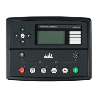
Identifies and labels the controls and indicators on the DSE6110 MKIII.
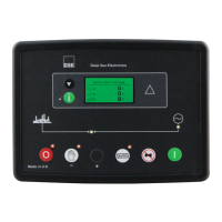
Identifies and labels the controls and indicators on the DSE6120 MKIII.
Provides detailed descriptions of the functions of each push button.
Explains how to navigate and view information on the module's display.
Describes the 'Status' page and its displayed information.
Explains the 'Generator Locked Out' status and how to clear it.
Explains the 'Waiting For Generator' status and how to check parameters.
Lists various engine parameters that can be monitored from the module.
Explains the Manual Fuel Pump Control feature accessible via the display.
Describes icons and their meanings for DPF regeneration status.
Lists electrical parameters related to the generator displayed by the module.
Shows measured values from connected input expansion modules.
Displays information and instrumentation for connected DSE Intelligent Battery Chargers.
Explains how alarms are activated, managed, and displayed.
Describes how ECU alarms (fault codes) are displayed on the module.
Explains how to view and navigate the module's event log.
Details the configuration to prevent shutdown/trip alarms from stopping the generator.
Describes the display of CAN information from external third-party devices.
Displays important information about the module and firmware versions.
Provides a quick start guide for operating the module.
Guides on starting the engine using the quickstart procedure.
Guides on stopping the engine using the quickstart procedure.
Explains how to use the Stop/Reset mode and its associated functions.
Describes the ECU override function available in Stop/Reset Mode.
Details how to operate the module in Manual Mode.
Explains the engine starting sequence in Manual Mode.
Describes engine running and load transfer in Manual Mode.
Explains loading requests and load removal when manual breaker control is disabled.
Explains loading requests and load removal when manual breaker control is enabled.
Details the engine stopping sequence in Manual Mode.
Details how to operate the module in Test Mode.
Explains the engine starting sequence in Test Mode.
Describes engine running and load transfer in Test Mode.
Details the engine stopping sequence in Test Mode.
Details how to operate the module in Automatic Mode for unattended operation.
Explains the module's state while waiting for a starting request in Auto Mode.
Explains the engine starting sequence in Automatic Mode.
Describes engine running and load transfer in Automatic Mode.
Details the engine stopping sequence in Automatic Mode.
Explains the scheduler for automatic start/stop sequences.
Describes how scheduled runs behave when the module is in Stop Mode.
Describes how scheduled runs behave when the module is in Manual Mode.
Describes how scheduled runs behave when the module is in Auto Mode.
Discusses selectable configurations like frequency settings provided by the supplier.
Explains how alarms are activated, managed, and displayed.
Details the configuration to prevent shutdown/trip alarms from stopping the generator.
Explains how to reset electrical trip alarms and inhibit stopping.
Describes how ECU alarms (fault codes) are displayed on the module.
Details non-critical warning alarms and their behavior.
Explains latching electrical trip alarms and their controlled shutdown process.
Details latching shutdown alarms that immediately stop the generator.
Explains maintenance alarm levels, triggers, and reset methods.
Describes the over current alarm combining warning and IDMT curve.
Explains the immediate warning alarm triggered when the trip level is reached.
Details the IDMT curve for thermal protection against overloads.
Guides on using spreadsheets to calculate IDMT curve tripping times.
Details the IDMT curve for protection against short circuits.
Guides on using spreadsheets to calculate IDMT curve tripping times for short circuits.
Explains the default IDMT tripping curves for over current and short circuit protection.
Details how to access and enter the main configuration editor.
Step-by-step instructions for accessing the main configuration editor.
Explains the procedure for entering the PIN code to access the editor.
Guides on selecting, editing, and saving parameters within the editor.
Explains how to exit the editor, with options to save or discard changes.
Lists parameters adjustable via the module's front panel configuration editor.
Lists all available output sources that can be assigned to digital outputs.
Explains how to access and edit parameters while the generator is running.
Step-by-step instructions for accessing the running configuration editor.
Explains that PIN is not requested for the running editor, but security measures apply.
Guides on editing parameters within the running configuration editor.
Explains how to exit the running editor and save changes.
Lists essential checks for wiring, supply, and mechanical parts before system start.
Provides an overview of instrumentation and control via CAN messages.
Lists parameter groups broadcast by DSE61XX modules under J1939-75.
Details the SPN for generator and utility circuit breaker status.
Details the SPN for generator automatic start status.
Details SPNs for average AC voltage, frequency, and current.
Details SPNs for Phase A AC voltage, frequency, and current.
Details SPNs for Phase A AC real and apparent power.
Details the SPN for Phase A AC reactive power.
Details SPNs for Phase B AC voltage, frequency, and current.
Details SPNs for Phase B AC real and apparent power.
Details the SPN for Phase B AC reactive power.
Details SPNs for Phase C AC voltage, frequency, and current.
Details SPNs for Phase C AC real and apparent power.
Details the SPN for Phase C AC reactive power.
Details the SPN for generator total AC percent power.
Details the SPN for generator total kW hours export.
Details the SPN for generator total kVAr hours export.
Details SPNs for generator total real and apparent power.
Details SPNs for generator total reactive power and power factor.
Lists broadcast messages for engine instrumentation parameters.
Details the SPN for fuel volume as a percentage of storage container.
Details the SPN for maximum crank attempts per start attempt.
Details the SPN for engine speed in RPM.
Details the SPN for crank attempt count on present start attempt.
Details the SPN for oil pressure in kPa.
Details the SPN for emergency stop status.
Details the SPN for engine coolant temperature in °C.
Details the SPN for engine total hours of operation.
Details SPNs for charge alternator and plant battery voltage.
Details SPNs and FMIs for active diagnostic trouble codes and alarm conditions.
Lists symptoms and remedies for engine starting issues.
Lists symptoms and remedies for generator not taking load.
Lists common alarms and their possible remedies.
Addresses issues related to communication failures, like ECU Data Fail.
Guides on resolving inaccurate measurements displayed on the controller.
Lists part numbers for purchasing additional connector plugs.
Lists part numbers for purchasing additional fixing clips.
Lists part numbers for purchasing the module silicon sealing gasket.
Lists available DSENet® expansion modules, their supported count, and part numbers.
Advises on the separate collection, treatment, and recycling of WEEE.
| Brand | DEEP SEA ELECTRONICS |
|---|---|
| Model | DSEGenset DSE6120 MKIII |
| Category | Control Unit |
| Language | English |