EasyManuals Logo

DEEP SEA ELECTRONICS DSEGenset DSE6120 MKIII User Manual

DEEP SEA ELECTRONICS DSEGenset DSE6120 MKIII
148 pages
To Next Page IconTo Next Page
To Previous Page IconTo Previous Page
Page #42 background imageLoading...
Page #42 background image
Installation
057-289 ISSUE: 1
Page 42 of 148
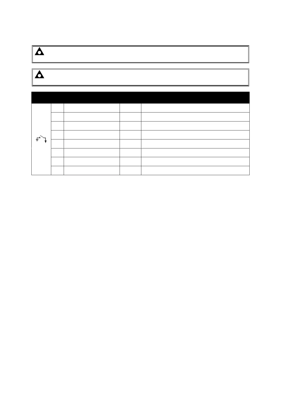
3.2.6 DIGITAL INPUTS
NOTE: For further details of module configuration, refer to DSE Publication: 057-290
DSE6110 MKIII & DSE6120 MKIII Configuration Suite PC Software Manual.
NOTE: A 120 Ω termination resistor must be fitted across terminals A and B if the DSE
module is the first or last device on the R485 link.
Pin
No
Description
Cable
Size
Notes
42
Configurable Digital Input A
0.5 mm²
AWG 20
Switch To Negative
43
Configurable Digital Input B
0.5 mm²
AWG 20
Switch To Negative
44
Configurable Digital Input C
0.5 mm²
AWG 20
Switch To Negative
45
Configurable Digital Input D
0.5 mm²
AWG 20
Switch To Negative
46
Configurable Digital Input E
0.5 mm²
AWG 20
Switch To Negative
47
Configurable Digital Input F
0.5 mm²
AWG 20
Switch To Negative
48
Configurable Digital Input G
0.5 mm²
AWG 20
Switch To Negative
49
Configurable Digital Input H
0.5 mm²
AWG 20
Switch To Negative

Table of Contents

Questions and Answers:

Question and Answer IconNeed help?

Do you have a question about the DEEP SEA ELECTRONICS DSEGenset DSE6120 MKIII and is the answer not in the manual?

DEEP SEA ELECTRONICS DSEGenset DSE6120 MKIII Specifications

General IconGeneral
BrandDEEP SEA ELECTRONICS
ModelDSEGenset DSE6120 MKIII
CategoryControl Unit
LanguageEnglish

Related product manuals