67
ENGLISH
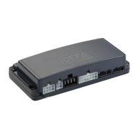
CONNECTIONS
Note: All inputs and outputs are programmable. Check the specic car installation guide for
changes to these connections.
Power Wires (P1)
Red wire (pin 1): Powers the alarm unit and the power outputs. Connect to a separate fuse
(25A) with permanent +12V source.
Blk wire (pin 3): Chassis ground to alarm unit. Connect to ground terminal.
Turn Signal Indication (P2)
Depending on the car, there are two ways of connecting the lights.*
Connecting to left and right turn signal lights.
Connect Gry/Red (Pin 4) and Gry/Blk (Pin 8) on P2 to the wires going to the left and right turn
signal lights.
Connecting to the Hazard switch.
Connect the General Purpose output used for controlling the hazard switch. This is car depen-
dent, normally Grn (Pin 2) or Blu/Red (Pin 7) on P2 is used.
* See the car specic installation guide for further details.
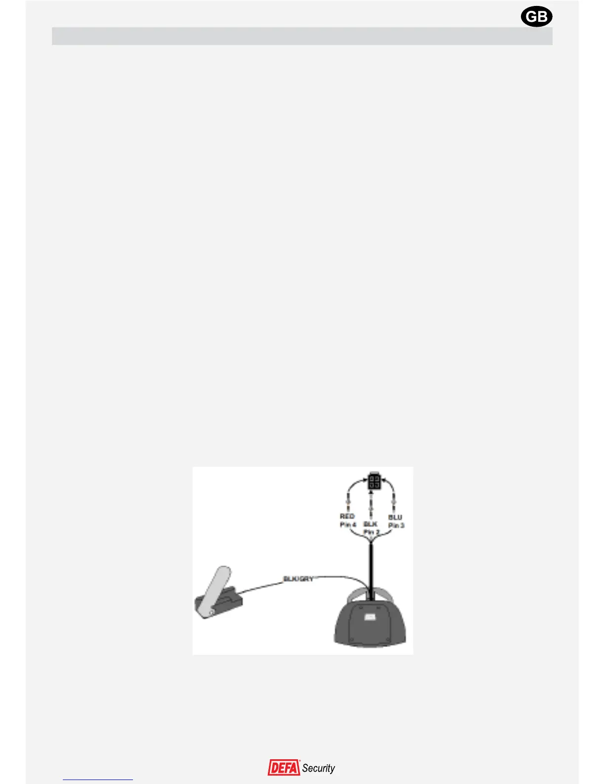
Siren
Install the siren in the engine compartment, exposed as little as possible to spray water and
heat from exhaust or turbocharger components (minimum distance 30 cm). The Siren aperture
must face downwards to prevent water accumulating in it.
The Siren must not be accessible from the underside of the car.
Pull the Red, Blk and Blu wires through the rewall and connect the wire to the enclosed con-
nector housing as follows:
Connect the wire to the LIN bus connector (P6 or P7) on the alarm unit. Do not use a LIN bus
splitter to the siren.
Leave the Blk/Gry wire in the engine compartment for connection of the hood switch.
Important: Never install the Siren with the aperture facing upwards.