Page 18 of 21 Tel.: (+45) 9614 9614 • Fax: (+45) 9614 9615 • E-mail: deif@deif.com
Guidelines for setting of the CSQ-3
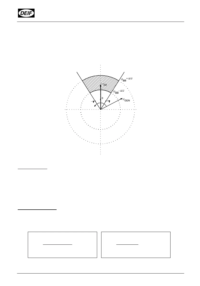
Visual representation of the parameters
The figure below shows the different parameters:
Commissioning
Normally t
R
is adjusted so it equals the circuit breakers closing time and ∆ϕ-/∆ϕ+ to
max. allowed synchronising error.
Please notice that the CSQ-3 calculates space for t
R
(breaker closing time) within the
chosen ∆ϕ window at the actual ∆f (slip frequency). Therefore the max. synchronising
error will never exceed the chosen ∆ϕ window.
Calculation example
The breaker closing time is 200mS, and t
R
is chosen to 200mS. The phase window is
set symmetrically to ±10° (electrical degrees). Then the max. ∆f can be calculated
using the following formula:
Synchronising relay pulse will not be emitted if ∆f exceeds 0.278Hz.
(∆ϕ-) + (∆ϕ+)
∆f =
360 x t
R
10 + 10
∆f = = 0.278Hz
360 x 0.2