5
Discharge Voltage Curve
To estimate battery voltage during a constant current
discharge at various DoD (Depth of Discharge) consult
chart Discharge Voltage Curve in Appendix B.
NOTE: Battery voltage can vary depending on temperature,
age and condition of battery.
To determine the correct system voltage, multiple the
number of cells connected in series by the above values.
The best way to determine if the battery needs an equalizing
charge is to check the specific gravity readings for each cell. If
there is more than 0.020 specific gravity unit variation between
any two cells, the battery should be equalized.
For installations in an uncontrolled temperature environment it is
highly recommended the Charge Controller / Inverter be used that
has voltage temperature compensation. Charging without voltage
temperature compensation can result in both under and over-
charging of the battery system resulting in reduced battery life and
may be a determining factor with
warranty claims.
Charge Current
To properly determine the amount of charge current required, the
following variables are to be considered:
• DoD (Depth of Discharge)
• Temperature
• Size & efficiency of the charger
• Age & condition of battery(ies)
Maximum charge current should be limited to 30% of the C20
Ah rate for the battery(ies) being used in the system.
Example: 8L16 C20 rate – 370Ah
Max. recharge rate: 370Ah x 0.3 = 111A
Calculating Recharge Time
The following can be used as a guideline for determining recharge
times:
85% to 90% SOC (State of Charge)
Time (hrs) = (Ahr x 1.2) / Ic
Note: Ic should be < 30% of C20
Ahr = Amp Hours removed during discharge.
Ic = Maximum current available to
battery from charger.
C20 = C20 rate in Ah
East Penn Mfg recommends returning 120% of Ah removed to
insure 100% SOC (State of Charge).
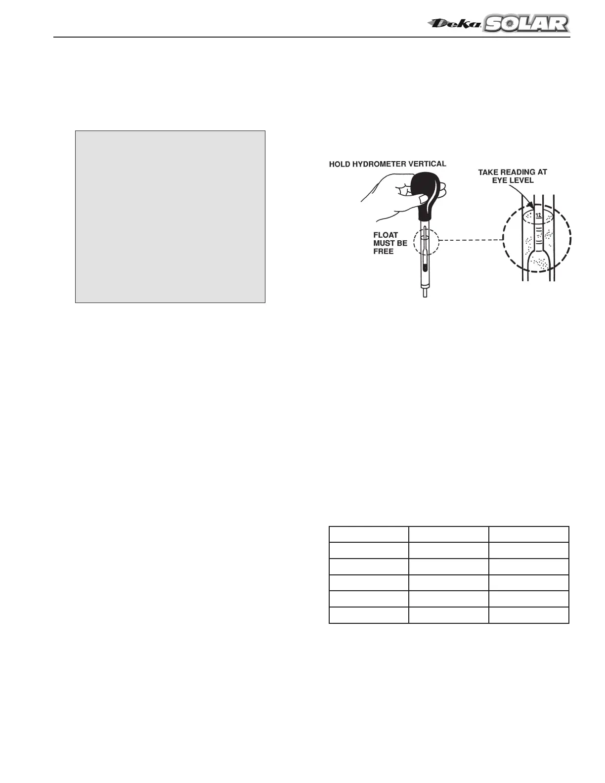
Specific Gravity Readings
The following applies when using a manual hydrometer. To take
a specific gravity reading, remove the cell’s vent cap, place the
rubber hydrometer nozzle into the vent opening and draw enough
electrolyte into the barrel to permit the float to rise freely. Hold the
hydrometer at eye level as shown below.
The correct hydrometer reading corresponds to an imaginary
line drawn across the side of the barrel at the lowest level of the
electrolyte. If the hydrometer has to be removed from the vent
hole, pinch the nozzle tightly or place a gloved finger against the
opening to prevent dripping.
Specific gravity measurements are based on a cell temperature
of 77°F (25°C). In order to obtain an accurate specific gravity mea-
surement, the hydrometer reading must be adjusted based on the
temperature of the electrolyte. A good rule of thumb for tempera-
ture correction is to add 4 points of specific gravity (.004) for each
10°F above 77°F and to subtract 4 points for each 10°F degrees
under 77° F (25°C).
To take the temperature reading, insert a thermometer into the
electrolyte of the pilot cell. If the thermometer doesn’t have specific
gravity/temperature corrections marked on it, refer to the above
paragraph.
Battery specific gravity and open circuit voltage can be used to
determine the SOC (State of Charge) of a battery.
The below chart details OCV & Specific Gravity to SOC:
For 6V battery divide voltage values by 2.
Note: True OCV of a battery can only be determined after
the battery has been removed from the load (charge or dis-
charge) for 24 hours.
CHARGING PARAMETERS
Bulk Charge:
Current limited to 30% of C20 or 6
times I20.
Absorption Charge:
14.40V to 14.70V
Float Charge:
13.80V to 14.10V
Equalize Charge:
15.00V to 15.30V
For 6V battery divide voltage values by 2
% SOC Specific Gravity OCV Voltage
100 1.265 12.66
75 1.225 12.44
50 1.190 12.25
25 1.155 12.06
0 1.120 11.87