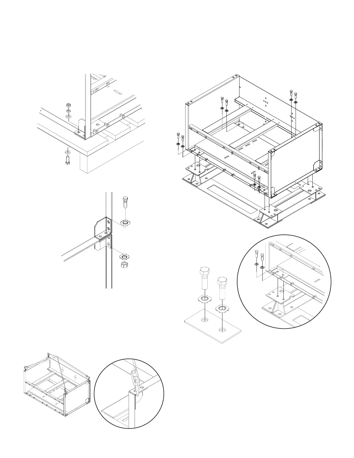
7. Base and module layout should be compared to system
layout diagram. All ½-13 x 1.75" hardware (2 per corner)
are to be installed on the inside of the module for module
t
o base connection. All hardware should be checked for
proper torque before proceeding. Star washers are to be
installed with teeth towards module to ensure proper
grounding. Consult “Hardware Torque Requirements”
(pg 5) for proper torque values.
SYSTEM INSTALLATIONS CONT.
5
. Remove hardware holding modules together (4 bolt
assemblies) and holding modules to pallet (4 bolt
assemblies). Hardware removed from module to
module will be reused to attach modules to modules.
Hardware holding modules to pallet can be discarded.
6. Install modules onto bases using supplied lifting straps.
Consult below diagram for proper sling attachment and
lifting. Consult included system layout diagram for module
position.
CAUTION: Never lift more than one module at a time
with the supplied lifting slings.
Module to Pallet Disassemble
Module to Module Separation
6
 Loading...