INSTALLATION
General
Caution should be taken when installing batteries to insure no
d
amage occurs. The battery cabinet, tray, rack, etc. shall be
inspected for sharp edges that could cause damage to the
battery casing. Batteries shall not be dropped, slid, or placed on
rough or uneven surfaces such as tray lips or grated flooring.
Mishandling of batteries could result in equipment damage or
h
uman injury. East Penn will not be liable for damage or injury
as a result of mishandling or misuse of the product.
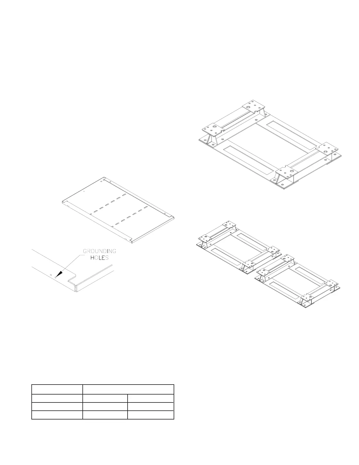
Grounding
When grounding the battery system, proper techniques should
be applied per electrical standards, such as NEC and/or local
codes. All module structural bolting connections are provided
with grounding washers. Two sets of 0.201 diameter x .750"
center holes are provided on the back side of the top plate to
accept a # 6 x .750 center compression grounding lug. The
holes must be tapped for a 1/4-20UNC thread and paint must
be removed for a proper grounding pad location. *
*Note: Battery system and/or individual module grounding, if
required, is the installer’s responsibility.
Electric Code for Maintenance Access Refer to ANSI/NFPA-
70 National Electric Code for access and working space
requirements around the battery. A minimum of 36" aisle
space is recommended in front of the battery for service and
inspection. Additional spacing may be required to meet
earthquake seismic requirements.
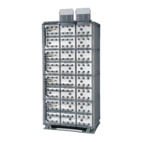
Module Arrangement See East Penn Mfg. Co.’s system layout
diagram. One is supplied with each shipment. If it cannot be
located, contact East Penn Mfg. Co. for a copy. Refer to your
delivery number, located on the packing slip. This will aid in
obtaining the proper diagram.
Hardware Torque Requirements
SYSTEM INSTALLATIONS
A
ll parts should be verified against packaging list.
Report any missing parts.
Module Installation
Assemble system per the following details.
1. Remove floor-mounting base support from module pallet.
2. Position base(s), consult included system layout diagram
for required configuration. Bases are required to be
level prior to installing modules.
3. Multiple stack systems should have a minimum of 4.00"
between bases. The additional spacing is for proper
installation of modules.
4. Anchor holes can be marked and drilled with bases in
place. All anchor holes in base (16 per base) are required
to be used to meet NEBS Zone 4 seismic requirements.
Anchors required to be installed prior to modules being
installed onto base. Reference Appendix A for base plate
anchor hole layout.
Consult local building codes for anchor bolt
requirements. Anchor bolts not included.
5
Bolt Size Torque/Retorque
1/2-13 100ft-lb 135.5 Nm
3/8-16 45ft-lb 61.0 Nm
1/4-20 125 in-lb 14.1 Nm
 Loading...