Star washers are to be installed with teeth towards module to
e
nsure proper grounding.
Note: Top Plate hardware contains two different types of star
washers. Consult below hardware diagrams for proper
installation.
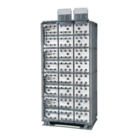
Retainer Bar Installation
1. Tier to Tier Retainer Bar Installation — Retainer bars
are to be installed per the below detail. All 3/8-16 x 1.25"
hardware should be checked for proper torque before
proceeding. Consult “Hardware Torque Requirements”
(pg 5) for proper torque values.
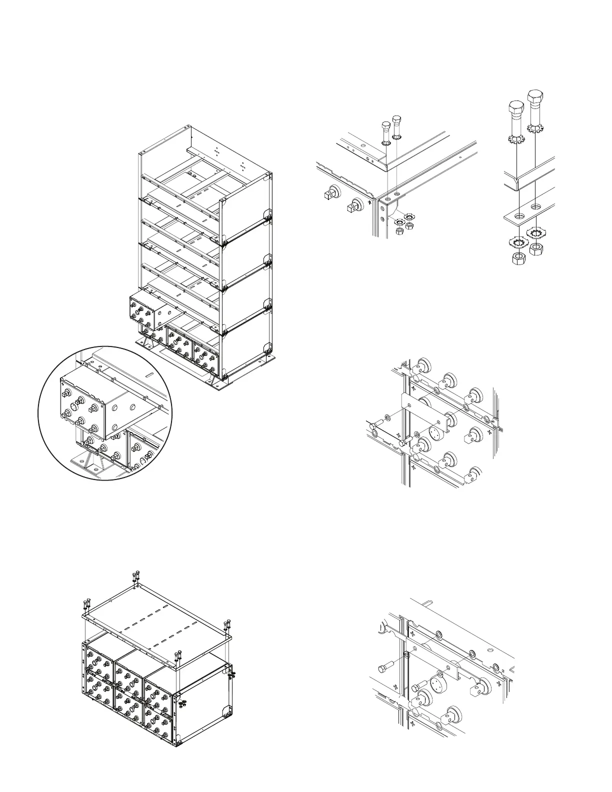
2. Top & Bottom Retainer Bar Installation — Retainer
bars are to be installed per the below detail. Top plate is to
be installed on the top module prior to installing top retain-
er bar. All 3/8-16 x 1.25" hardware should be checked for
proper torque before proceeding. Consult “Hardware
Torque Requirements” (pg 5) for proper torque values.
SYSTEM INSTALLATIONS CONT.
11. Cell / Sleeve Installation — Install cells into modules.
Cells are shipped separate from modules. Cell polarity
orientation responsibility of installer. Consult system
l
ayout diagram for cell location and polarity.
Care should be taken when installing cells that lifting
device does not contact previously installed cells
possibly causing a short.
12. Top Plate Installation — The top plate is to be installed on
the top module after all cell / sleeve assemblies have been
installed. Bolt assemblies (two per corner) are required on
the outside of the module to complete the top plate to mod-
ule connection. All ½-13 x 1.75" hardware should be checked
for proper torque before proceeding. Consult “Hardware
Torque Requirements” (pg 5) for proper torque values.
8
Tier to Tier Retainer Bar
Top Retainer Bar
 Loading...