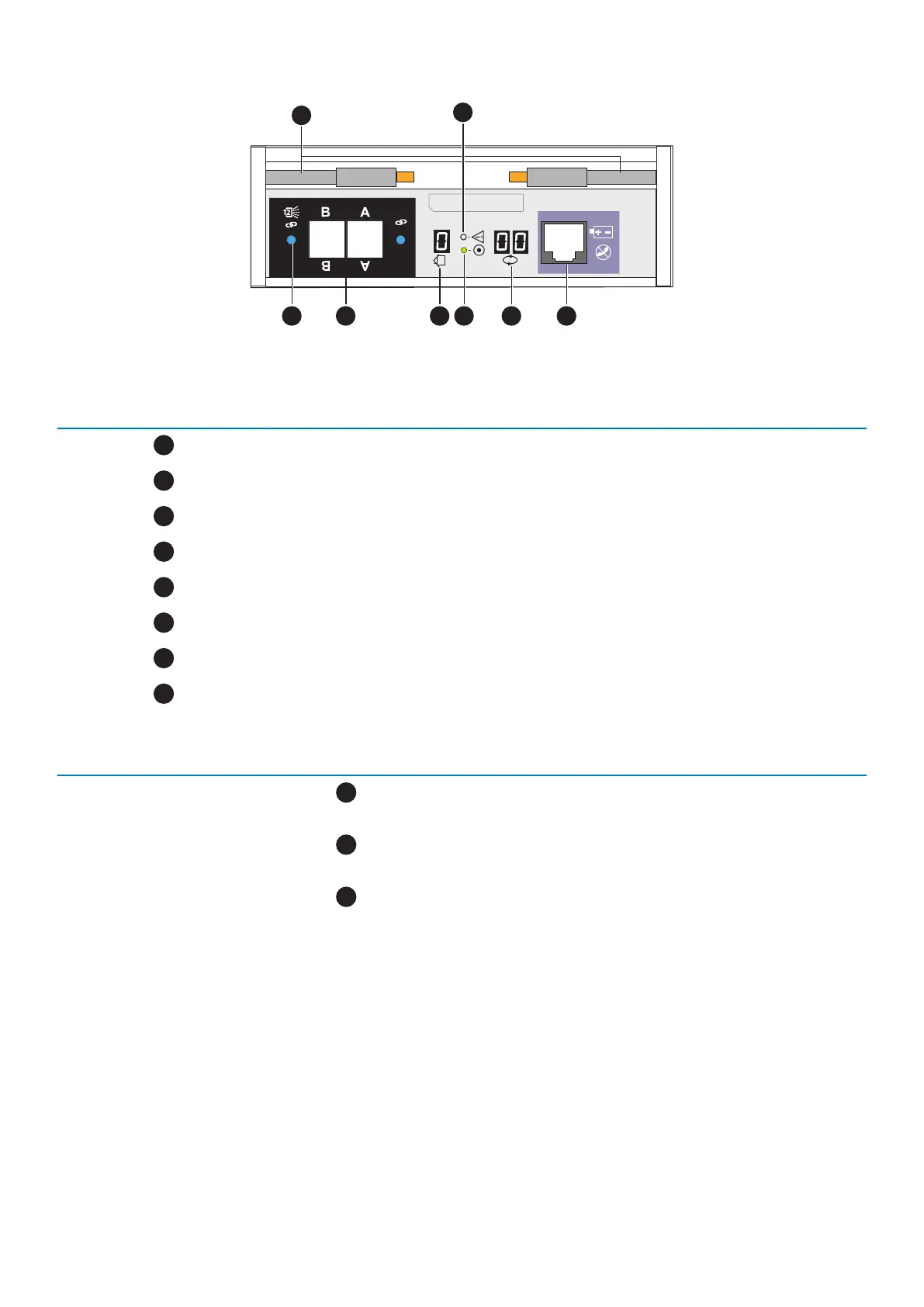
Figure 12. 2U, 25-drive expansion enclosure LCC ports, LEDs, and connectors
Table 10. 2U, 25 (2.5-inch) expansion enclosure LCC component locations
Location Description
Ejector latch handles
LCC fault LED
LCC management port (RJ-12) (not used)
Back-end bus ID display (always displays 01)
LCC power LED
Enclosure ID display
12-Gb/s SAS ports
SAS port status LED
Table 11. 12-Gb/s LCC LED status
LED Location Color State Description
LCC fault LED
Amber On Fault within the LCC
— Off No fault or powered off
LCC power LED
Green On Powered on and no fault
— Off Powered off
SAS port status LED
Amber On SAS port faulted
Blue On SAS port linked up
— Off No connector in port
2U, 25-drive expansion enclosure power supply and cooling module
Power supply and cooling module functions and features
The power supply and cooling modules are located to the left and right of the LCCs. The units integrate independent power supply and
two dual-blower cooling assemblies into a single module.
Each power supply is an auto-ranging, power-factor-corrected, multi-output, offline converter with its own line cord. Each power supply
supports a fully configured expansion enclosure and shares load currents with the other supply. The drives and LCCs have individual soft-
start switches that protect the drives and LCCs when they are installed while the expansion enclosure is powered on. The enclosure
cooling system includes two dual-blower modules.
16
Expansion enclosure component descriptions
 Loading...