8-104 Dell PowerEdge 2100/180 and 2100/200 Systems User’s Guide
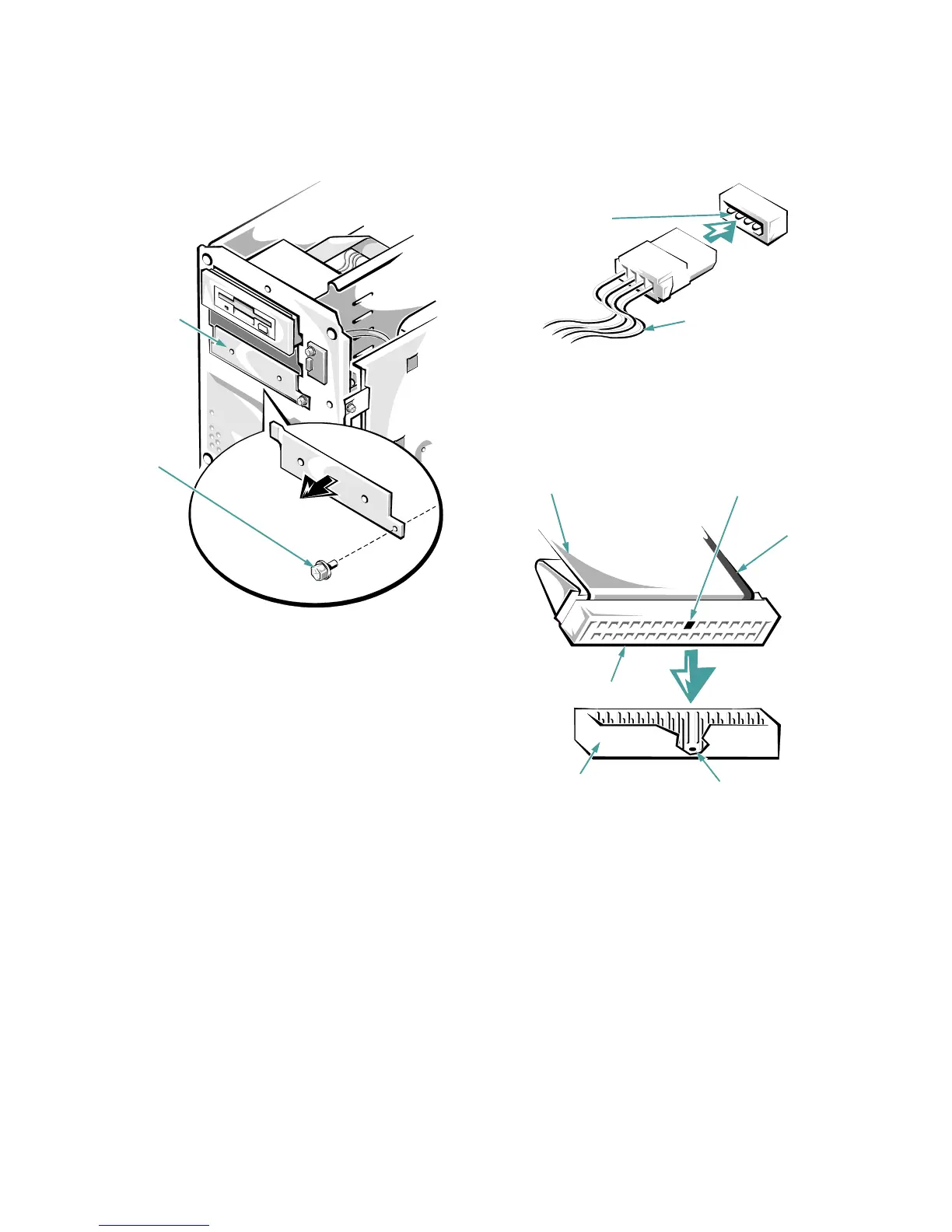
Figure 8-3. Removing a Metal Insert
Connecting the Drive
This section describes the power input connectors and
interface connectors on the back of most drives.
Figure 8-4 shows the 4-pin power input connector, where
you connect a direct current (DC) power cable from the
power supply. The power connectors are keyed to avoid
incorrect insertion; do not force two connectors together if
they do not fit properly.
Figure 8-4. Power Connectors
A ribbon cable (Figure 8-5) functions as the interface cable
for most types of drives.
Figure 8-5. Header Connector
Most interface connectors are keyed for correct insertion;
that is, a notch or a missing pin on one connector matches
a tab or a filled-in hole on the other connector. Keying
ensures that the pin-1 wire in the cable (indicated by the
colored strip along one edge of the cable) goes to the pin-1
ends of the connectors on both ends.
metal insert
retaining
screw
connector
on the drive
DC power cable (from
the power supply)
key (cut-off pin)
key (blocked hole)
header connector
interface connector
pull tab
colored
strip on
ribbon
cable