Installing System Board Options 7-85
Chapter 7
Installing System Board Options
This chapter describes installation of the following
options:
• Extended Industry-Standard Architecture (EISA),
Industry-Standard Architecture (ISA), and Periph-
eral Component Interconnect (PCI) expansion cards
• Dual in-line memory modules (DIMMs)
• Microprocessor upgrade
This chapter also includes instructions for replacing the
system battery, if necessary.
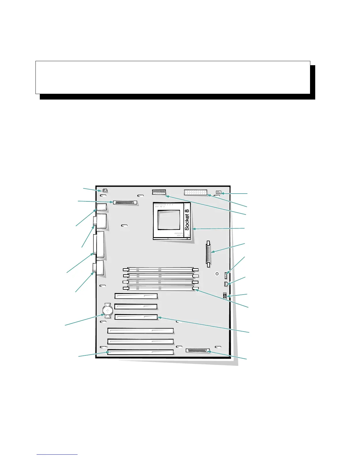
Use Figure 7-1 to locate the system board features.
Figure 7-1. System Board Features
video
connector (JVGA)
battery socket
(BATTERY)
parallel port
connector
(PARALLEL)
serial port 1 (bottom)
and serial port 2 (top)
connectors (SERIAL)
keyboard (bottom) and
mouse (top)
connectors
(KYBD/MOUSE)
diskette controller connector
(FLOPPY)
front-panel connector
(PANEL)
hard-disk drive access
indicator connector
(HDLED)
microprocessor
socket (PROCESSOR)
EISA connectors
(EISA1 [bottom],
EISA2, and EISA3)
fan connector (FAN)
power connector (POWER)
3-volt power connector
(POWER3V)
auxiliary fan connector
(AUXFAN)
DIMM sockets (DIMM_A
[bottom] DIMM_B, DIMM_C,
and DIMM_D)
PCI connectors (PCI4
[bottom], PCI5, and
PCI6)
server management
connector (SVR_MGT)
integrated SCSI port
connector (SCSI)
configuration jumpers