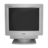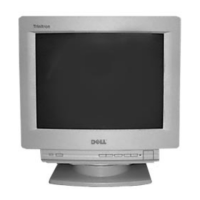
Do you have a question about the Dell D1025TM - UltraScan 1000HS - 17" CRT Display and is the answer not in the manual?
| Display Type | CRT |
|---|---|
| Screen Size | 17" |
| Maximum Resolution | 1280 x 1024 |
| Vertical Refresh Rate | 50 - 160 Hz |
| Dot Pitch | 0.25 mm |
| Input Signal | Analog RGB |
| Input Connector | 15-pin D-sub |
| Viewable Size | 15.9" |
| Refresh Rate | 85 Hz |
| Horizontal Refresh Rate | 30 - 85 kHz |
| Power Consumption | 90 Watts |
| Dimensions (W x H x D) | 16.1" x 16.1" x 17.1" |
AC leakage limits and measurement methods for exposed metal parts to earth ground.
Identification and explanation of the monitor's physical buttons and connectors.
Important warnings and precautions regarding power connection and usage.
Explanation of the On-Screen Display system for adjusting monitor settings.
Adjusting monitor color temperature using the COLOR OSD.
Adjusting picture centering using the CENTER OSD.
Enlarging or reducing the picture size using the ZOOM OSD.
Adjusting the picture size using the SIZE OSD.
Adjusting the picture's geometry using the GEOMETRY OSD.
Procedures for resetting specific or all monitor adjustments.
Common symptoms and their corresponding check items for problem resolution.
Step-by-step instructions for removing the monitor cabinet.
Procedure for placing the monitor in a service-safe position.
Instructions for removing the D and A circuit boards.
Detailed steps for safely removing the picture tube.
Checking and adjusting the High Voltage regulator for safety.
Verifying the HV hold-down circuit functionality.
Checking the beam protector function using software logic.
Checking the maximum B+ voltage under load.
Initial adjustment of the landing alignment for the electron beam.
Precise adjustment of the landing alignment using specialized equipment.
Initial adjustment of color convergence using magnets.
Precise adjustment of color convergence using magnets and testers.
Adjustments related to the 6-pole magnet for convergence.
Adjusting focus (V) and focus (H) for optimal picture clarity.
Digital adjustment of horizontal color convergence.
Digital adjustment of vertical color convergence.
Schematic diagram for the 'A' board of the monitor.
Schematic diagram for the 'D' board of the monitor.
Exploded view and parts list for the US/Canada chassis.
Exploded view and parts list for Japan/S. Hemisphere chassis.
List and diagram of packing materials used for all monitor models.
List of capacitors used in the monitor, with part numbers and specifications.
List of connectors used in the monitor, with part numbers.
List of diodes used in the monitor, with part numbers and specifications.
List of ferrite beads used in the monitor, with part numbers.
List of filters used in the monitor, with part numbers.
List of transistors used in the monitor, with part numbers and specifications.
List of resistors used in the monitor, with part numbers and specifications.
List of fuses used in the monitor, with part numbers and specifications.
List of integrated circuits used in the monitor, with part numbers.
List of transformers used in the monitor.
List of relays used in the monitor.