16. If the release lever on the socket is not fully extended, move it to that position now.
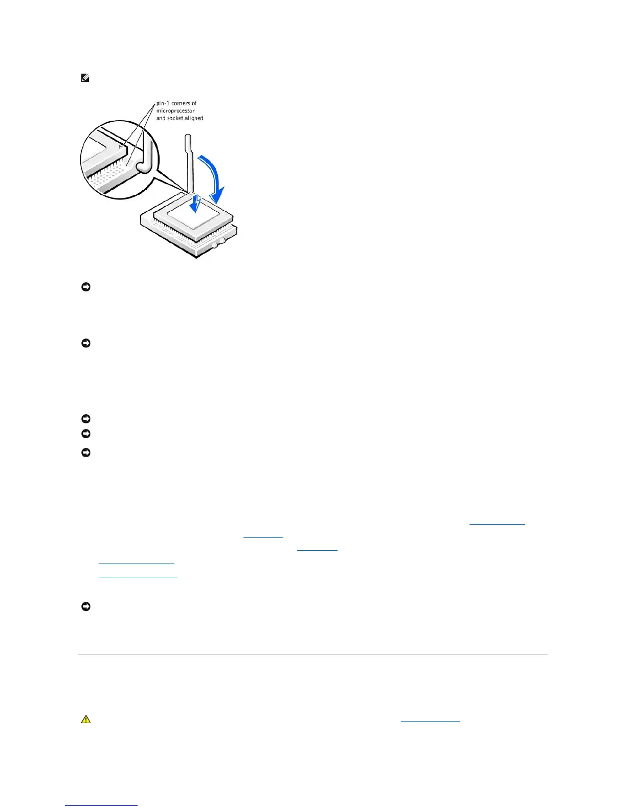
17. With the pin-1 corners of the microprocessor and socket aligned, align the pins on the microprocessor with the holes in the socket.
18. Set the microprocessor lightly in the socket and make sure that all pins are headed into the correct holes. Because your computer uses a ZIF socket,
there is no need to use force (which could bend the pins if the microprocessor is misaligned). When the microprocessor is positioned correctly, press it
with minimal pressure to seat it.
19. When the microprocessor is fully seated in the socket, pivot the release lever back toward the socket until it snaps into place, securing the
microprocessor.
20. Remove the film covering the thermal grease on the bottom of the heat sink.
21. Reinstall the two screws that attach the blower to the heat sink.
22. Lower the heat sink or blower/heat sink assembly to the microprocessor so that the heat sink fits in the retention base.
23. For each of the replacement securing clips, fit the end of the clip that does not have the latch over the tab on the retention base. Then, fit the middle of
the clip over the middle tab on the retention base, and press down on the clip's latch to secure the clip to the retention base (see the illustration).
24. Plug the fan cable into the FAN connector on the system board.
25. Plug the 12-volt power cable into the 12VPOWER connector on the system board.
26. Close the computer cover.
27. Attach the computer stand (optional).
28. Connect your computer and devices to their electrical outlets, and turn them on.
If you are installing a microprocessor replacement kit from Dell, return the original heat sink assembly and microprocessor package to Dell in the same package
in which your replacement kit was sent. Your microprocessor replacement kit should include a replacement microprocessor heat sink and one replacement
securing clip.
Replacing the System Board
Removing the System Board