Item Indicator, Button, or
Connector
Icon Description
10 USB connectors (2) Allow you to connect USB devices to the system.
The ports are USB 2.0-compliant.
11 System service tag/
Information tag
A slide-out label panel that allows you to record
system information such as Service Tag, NIC, MAC
address, and so on as per your need.
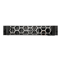
Back-Panel Features And Indicators
Figure 2. Back-Panel Features and Indicators
Item Indicator, Button, or
Connector
Icon Description
1 Serial connector Allows you to connect a serial device to the
system.
2 Dell PERC H310 slot Accommodates the Dell PERC H310 card.
3 Video connector Allows you to connect a VGA display to the
system.
4 eSATA Allows you to connect to an external storage
device for replication seeding.
NOTE: Do not connect a storage repository to
the eSATA connector.
5 USB connectors (2) Allow you to connect USB devices to the system.
The ports are USB 3.0-compliant.
6 Ethernet connectors (2) Two integrated 10/100/1000 Mbps NIC
connectors.
7 System status indicator Indicates the status of the system. Lights blue
during normal system operation. Lights amber
when the system needs attention due to a
problem.
8 System identification
button
The identification buttons on the front and back
panels can be used to locate a particular system
within a rack. When one of these buttons is
pressed, the system status indicator on the back
flashes until one of the buttons is pressed again.
Press to toggle the system ID on and off.
8

 Loading...