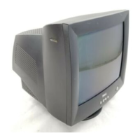
Do you have a question about the Dell E773c Series and is the answer not in the manual?
Guidelines for safely operating and handling the display, including electrical hazards and component care.
Important safety notices regarding component replacement and potential hazards like shock and fire.
Technical recommendations for servicing, including lead handling, resistor placement, and wire management.
Specific warnings about high voltage hazards during operation and servicing, including X-ray protection.
Conditions and precautions to follow before performing adjustments, including warm-up time.
List of main adjustments, their functions, locations on the PCB, and designations.
Procedures for performing various picture adjustments including timings, white balance, focus, and purity.
Details of the microcontroller IC, its core, memory, peripherals, and interfaces.
Explanation of the deflection circuit, including horizontal and vertical oscillators, and X-ray protection.
List of transistors and diodes with their locations and specific circuit functions.
Troubleshooting flowchart for no raster issues related to CRT circuits, power supply, and FBT.
Troubleshooting steps for abnormal display conditions like no signal on screen or abnormal video levels.
Diagnostic steps for horizontal, oscillator, deflection, and high voltage circuit faults.
Flowchart for diagnosing power supply output problems and variable output issues.
 Loading...