PS6610 Hardware Owner's Manual 1 Basic Storage Array Information
Item Indicator Description
Fault drawer 1
7 Drawer 2
Fault
Amber when a drive, cable, or sideplane fault has occurred in
drawer 2
Note: The LEDs are part of a built-in chassis control panel that is not hot-swappable and can be
replaced only by support personnel. During the array power-up sequence, these LEDs will cycle
through different states until the array is fully started and the active control module has been
determined.
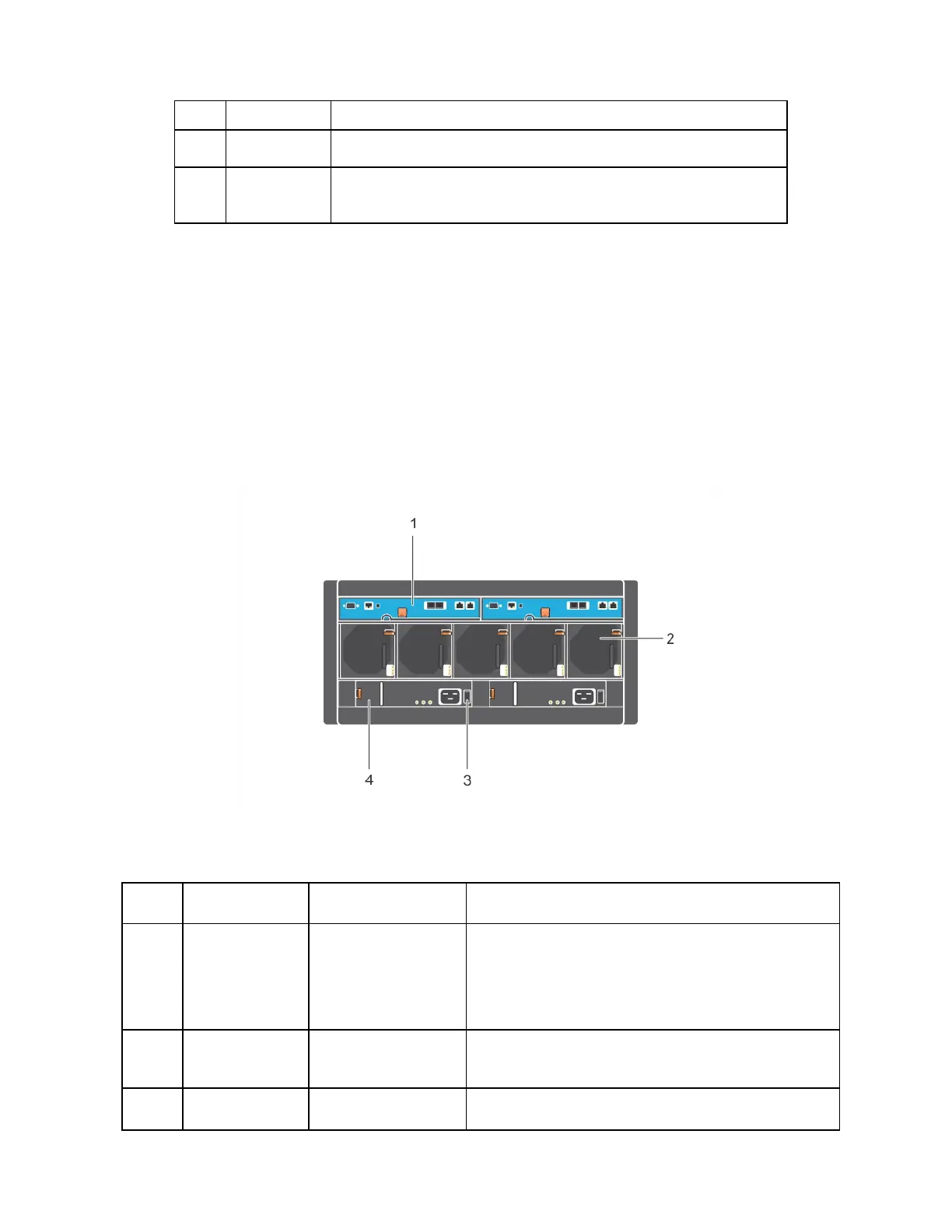
Back-Panel Features and Indicators
The back of a PS6610 is shown in Figure 5.
Table 4 describes the main features of the back panel.
Figure 5: Back-Panel Features
Table 4: Description of Back-Panel Features
Item Feature Identifier Description
1 Control Module
CM0 (left)
CM1 (right)
The control module provides:
• Connection to a data path between the array and
the applications using the storage
• Array management functions for your array
2 Cooling Fan
Modules
Modules are labeled
0-4 from left to right
Cooling fan module for array (5 total)
3 Power Switches None Controls power supply output to the array. Each
5

 Loading...