About this task
CAUTION: Before removing the system board, give sufficient time for the heat sink to cool down to avoid injury.
NOTE: Replacing the system board removes any changes that you have made to the BIOS using the BIOS setup program.
Make the appropriate changes again after you replace the system board.
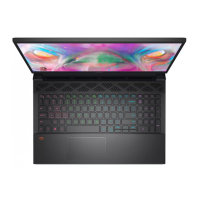
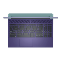
The following image indicates the connectors on your system-board assembly.
1. Display cable
2. Dynamic-display switch (DDS) cable (applicable to computers with a 165 Hz or 240 Hz display)
3. Power-adapter port cable
4. Right-fan cable
5. Touchpad cable
6. Keyboard cable
7. Keyboard-backlight cable
8. Keyboard-controller board cable (optional)
9. Left-fan cable
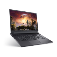
The following image indicates the location of the system board and provides a visual representation of the removal procedure.
Removing and installing Field Replaceable Units (FRUs)
67
 Loading...