12. Remove the assembly inner frame.
About this task
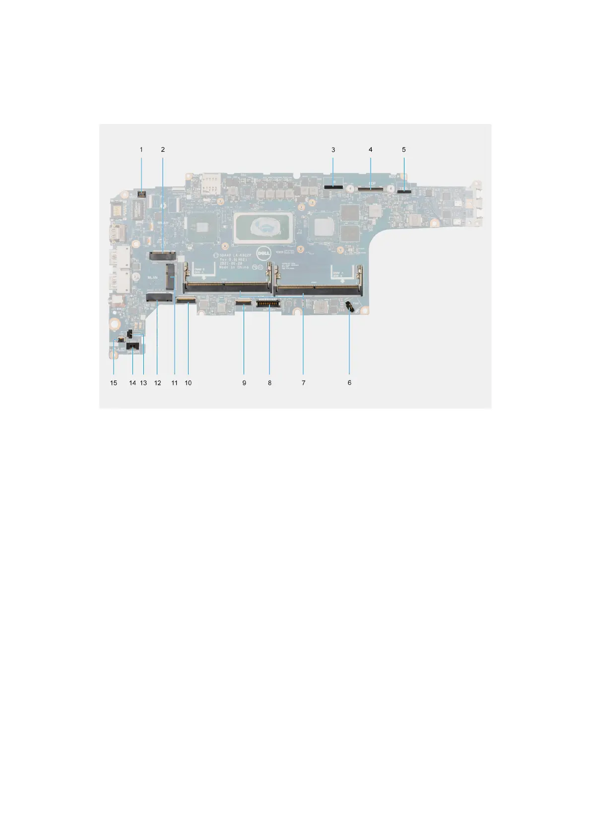
The following image indicates the connectors on your system board.
Figure 1. System board connectors
1. Fingerprint reader connector
2. WWAN connector
3. Camera/IR cable connector
4. eDP/display cable connector
5. Touch and sensor cable connector
6. Memory modules
7. Battery cable connector
8. Clickpad cable connector
9. USH board connector
10. WLAN connector
11. Solid-state drive slot
12. Coin-cell battery cable connector
13. Speaker cable connector
14. System fan connector
15. Battery LED cable connector
The following images indicate the location of the system board and provide a visual representation of the removal procedure.
Removing and installing components
51