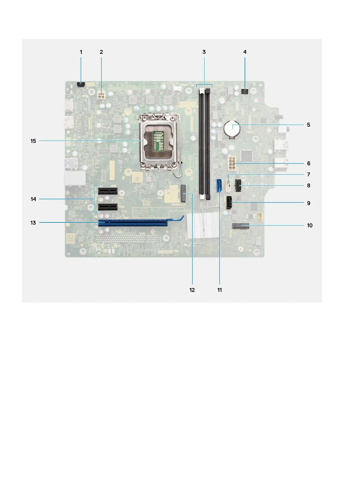
1. Intrusion switch connector
2. ATX CPU power connector
3. Memory module connectors
4. Power switch connector
5. Coin-cell battery
6. System power connector
7. SATA connector (white)
8. SATA power cable connector
9. SATA1 connector
10. M.2 WLAN connector
11. SATA0 connector (blue)
12. M.2 PCIe SSD connector
13. PCIe x16 (Slot3)
14. PCIe x1 (Slot1/2)
15. Processor socket
The following images indicate the location of the system board and provide a visual representation of the installation procedure.
86
Removing and installing components