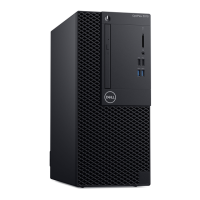
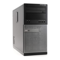
Do you have a question about the Dell OptiPlex 390 Mini-Tower and is the answer not in the manual?
Safety guidelines and conditions for working inside the computer.
Lists essential tools for performing procedures within the computer.
Steps to safely shut down the computer before internal work.
Steps to reconnect and verify the computer after internal procedures.
Step-by-step instructions for removing the computer chassis cover.
Step-by-step instructions for reinstalling the computer chassis cover.
Instructions for detaching the front bezel from the computer chassis.
Instructions for reattaching the front bezel to the computer chassis.
Steps to remove various types of expansion cards from the computer.
Steps to install various types of expansion cards into the computer.
Instructions for removing the optical drive from the computer.
Instructions for installing the optical drive into the computer.
Steps to remove the hard drive from its bay and bracket.
Steps to install the hard drive into its bracket and bay.
Instructions for removing memory modules from the system board slots.
Instructions for installing memory modules into the system board slots.
Steps to remove the chassis intrusion switch from the system board.
Steps to install the chassis intrusion switch onto the system board.
Instructions for removing the internal speaker from the computer chassis.
Instructions for installing the internal speaker into the computer chassis.
Steps to remove the heat sink and processor assembly from the system board.
Steps to install the heat sink and processor assembly onto the system board.
Instructions for removing the coin-cell battery from its socket.
Instructions for installing the coin-cell battery into its socket.
Steps to disconnect and remove the power switch cable from the system.
Steps to connect and install the power switch cable to the system.
Steps to disconnect and remove the front thermal sensor.
Steps to connect and install the front thermal sensor.
Instructions for removing the chassis fan from the computer.
Instructions for installing the chassis fan into the computer.
Steps to disconnect and remove the front input/output panel.
Steps to install the front input/output panel.
Steps to disconnect and remove the power supply unit from the computer.
Steps to install the power supply unit into the computer.
Steps to disconnect cables and remove the system board.
Steps to place, secure, and connect the system board.
Accessing and basic options within the computer's BIOS setup.
Using the boot menu to select boot devices for a single boot session.
Details on improved access and options for the boot menu.
Explains beep codes and text error messages displayed by the BIOS.
Keystrokes used to navigate the BIOS setup screens.
Overview of general system information and configuration settings.
Setting the order of devices for operating system startup.
Configuring the system's date and time settings.
Enabling or disabling the integrated network card and its options.
Configuring the serial port settings.
Configuring the operating mode of the integrated hard drive controller.
Enabling or disabling onboard drives.
Controlling hard drive error reporting during startup.
Enabling or disabling the integrated USB controller features.
Enabling or disabling the Wi-Fi radio.
Setting restricted access to system setup programs.
Managing system and internal HDD password security.
Checking the status of the system's internal hard disk drive password.
Enabling or disabling strong password enforcement.
Setting password length requirements.
Bypassing password prompts during restarts.
Permitting password changes when an administrator password is set.
Enabling or disabling the Computrace Service for asset management.
Controlling the chassis intrusion detection feature.
Enabling or disabling the processor's Execute Disable mode.
Controlling access to OROM configuration screens via hotkeys.
Locking out setup entry when an administrative password is set.
Enabling or disabling processor cores.
Enabling or disabling Intel SpeedStep processor technology.
Enabling or disabling additional processor sleep states.
Enabling or disabling Intel Hyper-Threading Technology.
Defining system response to AC power restoration after an outage.
Setting a scheduled time for the computer to turn on automatically.
Defining controls when Deep Sleep mode is enabled.
Controlling the speed of the system fan.
Enabling the computer to power up via a LAN signal.
Enabling or disabling the Numlock feature at startup.
Enabling or disabling keyboard error reporting during startup.
Specifying function keys to display during POST.
Speeding up the boot process by bypassing compatibility checks.
Enabling Virtual Machine Monitor hardware capabilities.
Enabling or disabling direct I/O virtualization capabilities.
Displaying the computer's Service Tag.
Creating a system asset tag.
Controlling the SERR message mechanism for graphics cards.
Specifying how the ImageServer looks up the server address.
Setting the primary static IP address for the ImageServer.
Setting the primary IP port for the ImageServer.
Specifying how the client obtains its IP address.
Setting the static IP address for the client.
Setting the subnet mask for the client.
Setting the gateway IP address for the client.
Displaying the current license status.
Displaying system event logs and options to clear or mark entries.
Explains the function and location of diagnostic LEDs for POST status.
First pattern: computer off or not receiving power.
Second pattern: possible system board failure.
Third pattern: system board, power supply, or peripheral failure.
Fourth pattern: memory power failure detected.
Fifth pattern: BIOS may be corrupt or missing.
Sixth pattern: possible system board failure.
Seventh pattern: power connector not installed properly.
Eighth pattern: possible peripheral or system board failure.
Ninth pattern: possible system board failure.
Tenth pattern: possible coin cell battery failure.
Eleventh pattern: possible processor failure.
Twelfth pattern: memory detected, but failure.
Thirteenth pattern: possible hard drive failure.
Fourteenth pattern: possible USB failure.
Fifteenth pattern: no memory modules are detected.
Sixteenth pattern: memory configuration or compatibility error.
Seventeenth pattern: possible expansion card failure.
Eighteenth pattern: system board resource/hardware failure.
Nineteenth pattern: some other failure has occurred.
Explains the meaning and cause of various beep codes.
Lists and describes error messages encountered during system operation.
Details about the system chipset, DMA channels, interrupts, and BIOS.
Information on processor type and cache.
Details on memory type, speed, connectors, capacity, and cache.
Specifications for integrated and discrete video types and memory.
Details on the integrated audio codec.
Specifications for the integrated network interface controller.
Details on bus types and speeds for PCI Express, SATA, and USB.
Information on PCI Express x1 and x16 card slots.
Specifications for externally accessible and internally accessible drive bays.
Details on audio, network, and USB connectors.
Specifications for back panel video connectors.
Details on system board connectors like PCI Express, SATA, PS/2, memory, and fans.
Details on password jumpers, RTC reset, speaker, intruder, and power connectors.
Information on front and back panel lights and their meanings.
Details power system self-test and specifications for power, wattage, and voltage.
Physical dimensions (height, width, depth, weight) for different form factors.
Environmental operating conditions like temperature, humidity, vibration, and shock.
Instructions and website for contacting Dell support.
| RAM | Up to 16GB DDR3 |
|---|---|
| Storage | Up to 1TB HDD or 256GB SSD |
| Form Factor | Mini-Tower |
| Audio | Integrated HD audio |
| Processor | Intel Core i3, i5, or i7 (2nd generation) |
| Graphics | Integrated Intel HD Graphics |
| Operating System | Windows 7 |
| Ports | USB 2.0, VGA |
| Chipset | Intel Q65 Express |
| Optical Drive | DVD-ROM |
| Networking | Gigabit Ethernet |
| Slots | PCIe x16, PCIe x1 |
