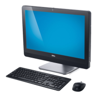
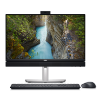
Removing and installing components
NOTE: The images used in this chapter are leveraged from the OptiPlex 7480 All-in-One model for illustration purpose
and may slightly vary from the actual system. The images are still applicable to convey the service procedures
accurately.
Topics:
• Recommended tools
• Screw list
• Stand
• Cable cover—optional
• Back cover
• Hard drive
• Memory modules
• System-board shield
• Solid-state drive
• System fan
• Coin-cell battery
• Wireless card
• Camera assembly
• Bottom cover
• Power-supply unit
• Power-supply fan
• Heat sink
• Processor
• Rear-I/O bracket
• System board
• Speakers
• Power-button board
• Microphones
• Side I/O-board
• Audio board
• Antenna modules
• Display panel
• Middle frame
Recommended tools
The procedures in this document may require the following tools:
• Phillips screwdriver #1
• Plastic scribe
Screw list
NOTE:
When removing screws from a component, it is recommended to note the screw type, the quantity of screws,
and then place them in a screw storage box. This is to ensure that the correct number of screws and correct screw type
is restored when the component is replaced.
NOTE: Some systems have magnetic surfaces. Ensure that the screws are not left attached to such surface when
replacing a component.
2
10 Removing and installing components
 Loading...
