1. Power-supply unit (PSU) cable connector
2. Coin-cell battery
3. Display back-light cable connector
4. Camera cable connector
5. M.2 2230/2280 solid-state drive connector
6. Processor-fan cable connector
7. Memory modules
8. Hard-drive connector
9. Side I/O-signal cable connector
10. Side I/O-power cable connector
11. Audio-board cable connector
12. Microphone-module cable connector
13. Speaker cable connector
14. Power-button cable connector
15. Display cable connector
16. M.2 WLAN connector
17. PSU-fan cable connector
18. Touchscreen cable connector
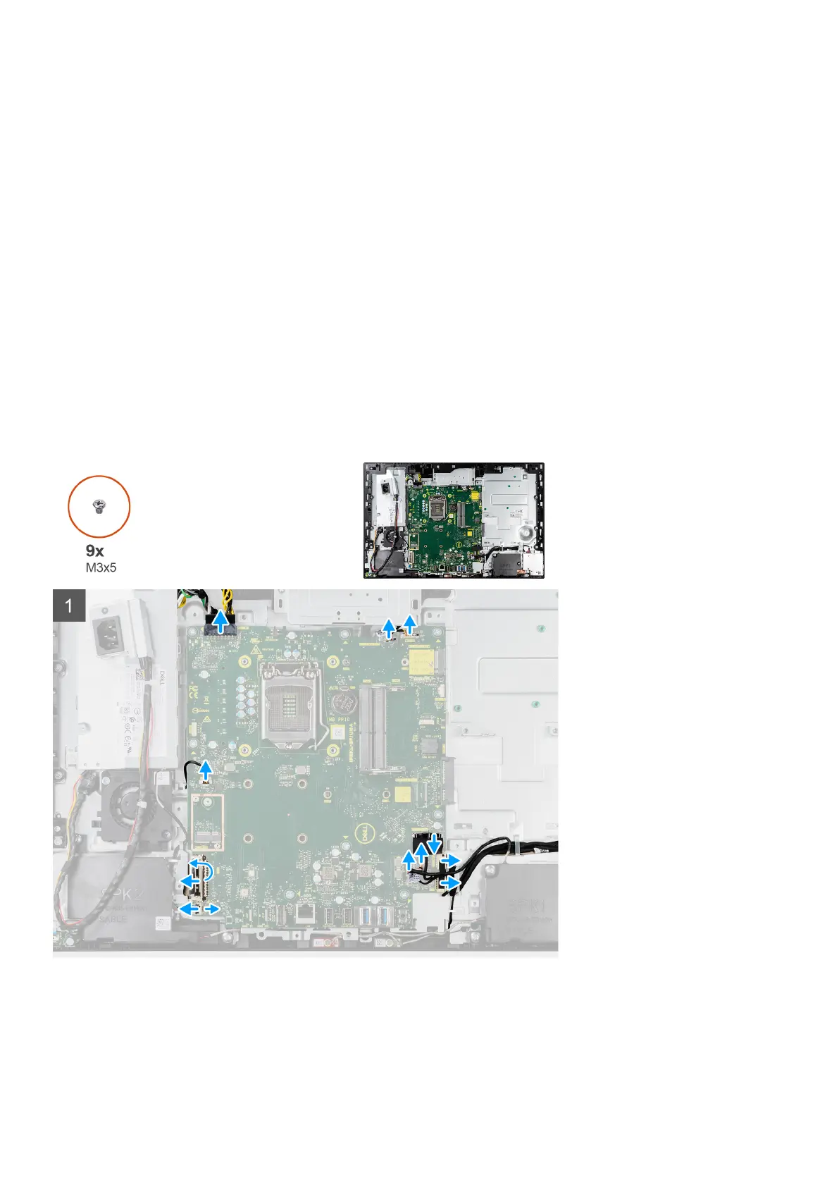
19. Processor
The following image indicates the location of the system board and provides a visual representation of the removal procedure.
60 Removing and installing components