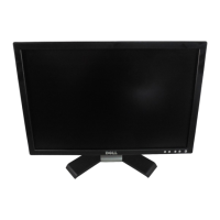
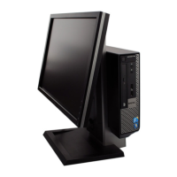
Table 3. Number of jig screws (continued)
Display type Number of jig screws
Non-touch
display
Three
6. Route the display back-light cable in the routing guides on the display-assembly base.
Next steps
1. Install the PSU fan.
2. Install the PSU.
3. Install the system board.
4. Install the camera assembly.
82
Removing and installing components