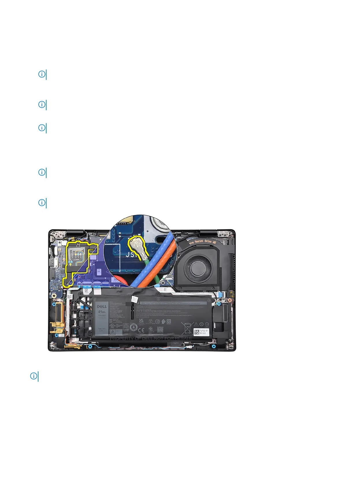
13. Remove the display-cable bracket from the system board.
14. Peel back the tape that secures the display cable to the system board.
15. Disconnect the following cables from the respective connectors on the system board:
a. Touch-screen cable, if applicable
NOTE: This step applies only to computers shipped with a touch screen installed.
b. Display cable
c. IR-camera cable, if applicable
NOTE: This step applies only to computers shipped with an IR camera installed.
d. Sensor daughter-board cable, if applicable
NOTE: This step applies only to computers shipped with a sensor daughter-board installed.
e. Speaker cable
f. Audio daughter-board FFC
g. Touchpad FFC
h. USH daughter-board FFC, if applicable
NOTE: This step applies only to computers shipped with a USH daughter-board installed.
i. LED daughter-board FFC
j. P-sensor cable
NOTE: This step applies only to computers shipped with 5G antennas installed.
16. Remove the three screws (M2x2.5), the two screws (M2x4) and the two screws (M2x3) that secure the system board to
the palm-rest and keyboard assembly.
NOTE: This step applies only to computers shipped with a power button with fingerprint reader installed.
76 Removing and installing components