Stacking Dell PowerConnect Switches: 8132, 8132F, 8164, 8164F
12
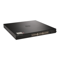
10Gbase-T four-port expansion module for the Dell PowerConnect 81xx and 81xxF
Figure 5.
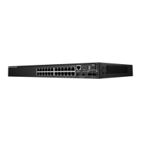
40G QSFP+ two-port expansion module for the Dell PowerConnect 81xx and 81xxF Figure 6.
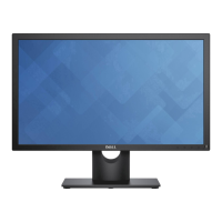
10G SFP+ four-port expansion modules for the Dell PowerConnect 81xx and 81xxF
Figure 7.
With an expansion module installed, the command show switch stack-ports shows the link
status, link speed, and stack mode for each port in the module.
Creating a Stack
Examples below provide steps on how to create a stack. Graphics shown in this section only depict
some of the possibilities of how to cable together members of a stack.
Note: While the cable pictures below come before the configuration steps, it is important not
to cable the stack until instructed to do so.
Cabling is one of the last steps and comes after configuring all switches used in the stack; however, it
is necessary to know exactly each port that is going to be cabled to configure each switch correctly.
The Dell PowerConnect 8100 series switches can be stacked up to six high, supporting up to 336x10G
ports when two 40G ports on each unit are configured as stacking ports. The stack can contain any
combination of Dell PowerConnect 8100 and Dell PowerConnect 8100F switches.
The switches can be stacked using any Ethernet port on the front panel, which includes 40Gb QSFP+
ports, 10Gb SFP+ fiber ports, and 10Gb baseT copper ports. Each of these default to Ethernet mode
and must be reconfigured as stacking ports in order to stack.
This scenario shows steps to create a stack. Figure 8 shows one example of connectivity between stack
members.
 Loading...