Do you have a question about the Dell POWERCONNECT 5524 and is the answer not in the manual?
This guide describes how to install and run the PowerConnect 5500 series switches.
Verifies location requirements for installing the switch, including power, clearance, cabling, and ambient conditions.
Provides instructions for unpacking the switch and checking package contents.
Details methods for installing the switch, including rack mounting and flat surface placement.
Describes how to connect the switch to AC and optional Redundant/Modular Power Supplies.
Explains the concept of switch stacking, including master and member units, and stack limits.
Instructions on physically connecting switches using HDMI cables for stacking.
Details how to assign unique IDs to switches in a stack, covering automatic and manual methods.
Outlines the steps involved in configuring the switch after installation and stacking.
Guides on establishing a console connection to the switch for configuration using terminal emulation.
Describes the power-on self-test (POST) process and the expected LED status after booting.
Explains how to configure the entire stack of switches.
Details the use of the Setup Wizard for initial switch configuration.
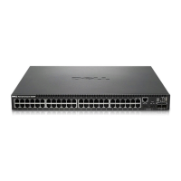
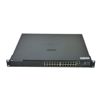
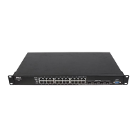
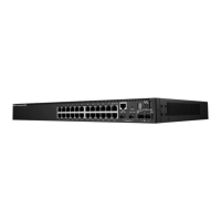
The Dell PowerConnect 5500 Series is a line of network switches designed for various networking environments, offering robust functionality for both single-switch setups and stacked configurations. This Getting Started Guide, along with the comprehensive User Guide, provides detailed instructions for installation, configuration, and ongoing management of these devices. The switches are suitable for deployment in standard 19-inch equipment racks or as standalone units on a tabletop, providing flexibility in installation.
The primary function of the Dell PowerConnect 5500 Series switches is to facilitate network connectivity and data transfer within a local area network (LAN). These devices are capable of handling network traffic efficiently, supporting various protocols and management features to ensure reliable operation. The switches can operate as individual units or be combined into a stack, allowing for scalability and increased port density. In a stacked configuration, one switch acts as the "Master" unit, responsible for managing the entire stack, while others can function as "Master Backup" or "Member" (slave) units. This hierarchical structure ensures redundancy and simplifies management of multiple switches as a single logical entity.
The PowerConnect 5500 Series switches are equipped with HDMI 10G ports specifically for stacking purposes, enabling high-bandwidth connections between stacked units. This design not only enhances data throughput but also provides redundancy, as the stack can continue to operate even if one of the stacking links fails. The switches support various power options, including standard AC power and, optionally, Redundant Power Supply (RPS) or Modular Power Supply (MPS) units for enhanced reliability and continuous operation. The RPS/MPS connectors are located on the back panel, ensuring easy access for power connections.
Configuration of the switches can be performed through a terminal connection using an RS-232 cable, which connects to a console port on the front panel. This allows for initial setup, command-line interface (CLI) access, and execution of the Setup Wizard. The Setup Wizard is a guided process designed to simplify the initial configuration, covering essential settings such as SNMP community string, management IP address, username, password, IP subnet mask, and default gateway. For more advanced management, the switches can be configured via Telnet, web GUI, or CLI, as detailed in the Dell PowerConnect 5500 Series User Guide.
The Dell PowerConnect 5500 Series offers several features that enhance its usability and adaptability in different network environments. The ability to stack up to eight switches provides significant scalability, allowing network administrators to expand their network capacity as needed without introducing additional management complexity. The stacking architecture treats multiple physical switches as a single logical unit, simplifying configuration and monitoring. The use of HDMI 10G ports for stacking ensures high-speed inter-switch communication, crucial for demanding network applications.
Installation is straightforward, whether mounting in a rack or placing on a flat surface. The rack-mounting kit includes brackets and screws, and clear instructions are provided for secure installation. For tabletop placement, self-adhesive rubber pads are included to prevent slippage and protect surfaces. Proper site preparation is emphasized, including considerations for power accessibility, adequate clearance for cabling and ventilation, and ambient environmental conditions (temperature and humidity) to ensure optimal performance and longevity of the device.
The initial setup process is streamlined with the Setup Wizard, which guides users through critical configuration steps. This wizard is particularly useful for first-time installations or when a switch has been reset to factory defaults. It prompts for essential network parameters and management credentials, making the switch ready for basic operation quickly. Users have the option to skip the wizard and perform manual configuration via the CLI for more granular control.
Unit ID assignment is a key feature for stacked configurations. Each switch in a stack is assigned a unique Unit ID, which defines its role and position within the stack. This assignment can be automatic upon power-up, with Unit ID 1 typically becoming the Master and Unit ID 2 the Master Backup. Alternatively, manual assignment is possible through the Start Up menu accessed via the console, allowing administrators to explicitly define the Unit ID for each switch. This flexibility helps in organizing and managing complex stack topologies.
The front panel LEDs provide visual feedback on the switch's operational status, including power, system status, fan operation, and RPS status. During the boot process, the power-on self-test (POST) verifies hardware components, and the LEDs indicate successful completion or potential issues. The stacking LEDs specifically show the assigned Unit ID and the Master status, aiding in quick identification of each switch's role in a stack.
Maintenance of the Dell PowerConnect 5500 Series switches is designed to be user-friendly and efficient. The modular design, particularly with optional RPS/MPS units, allows for easy replacement of power supplies, minimizing downtime in case of a power component failure. The emphasis on proper site preparation, including adequate ventilation and clearance, contributes to the longevity of the device by preventing overheating and ensuring accessibility for routine checks.
The documentation provided, including the Getting Started Guide and the Dell PowerConnect 5500 Series User Guide, serves as a comprehensive resource for troubleshooting and maintenance. These guides contain detailed information on advanced functions, configuration options, and best practices for managing the switches. Dell also provides support through its website, offering the latest documentation updates and software releases, which are crucial for keeping the device secure and performing optimally.
The ability to access the switch via a console port, Telnet, or web GUI provides multiple avenues for remote and local management, facilitating maintenance tasks such as firmware upgrades, configuration backups, and diagnostic checks. The CLI offers powerful tools for detailed system monitoring and configuration adjustments, while the web GUI provides an intuitive graphical interface for less experienced users.
In the event of a problem, the boot process includes a power-on self-test (POST) that helps diagnose hardware issues. If a critical problem is detected, the boot process stops, indicating a need for attention. The status LEDs on the front panel provide immediate visual cues regarding the health of the switch, allowing administrators to quickly identify and address issues.
For stacked configurations, the redundancy provided by the HDMI 10G stacking ports ensures that the network remains operational even if one of the links is compromised. This built-in resilience reduces the impact of single points of failure, which is a significant maintenance advantage. The ability to manually assign Unit IDs also aids in maintaining a consistent and predictable stack configuration, simplifying management and troubleshooting over time.
Regular checks of the ambient operating environment, as specified in the site requirements (temperature and humidity), are important to prevent environmental stress on the hardware, thereby extending its operational life and reducing the need for premature maintenance or replacement. Adhering to cabling guidelines, such as avoiding sources of electrical noise, also contributes to stable and reliable network performance, minimizing potential issues that would require troubleshooting.
| MAC address table | 16000 entries |
|---|---|
| Jumbo frames support | Yes |
| Packet buffer memory | 12 MB |
| Maximum data transfer rate | 10 Gbit/s |
| Supported data transfer rates | 10/100/1000 Mbps |
| Number of VLANs | 4000 |
| Networking standards | IEEE 802.1ab, IEEE 802.1D, IEEE 802.1p, IEEE 802.1Q, IEEE 802.1v, IEEE 802.1w, IEEE 802.1x, IEEE 802.3, IEEE 802.3ac, IEEE 802.3ad, IEEE 802.3u, IEEE 802.3x, IEEE 802.3z |
| Dimensions (WxDxH) | 440 x 255 x 432 mm |
| Connectivity technology | Wired |
| Switch type | Managed |
| Switch layer | L3 |
| SFP/SFP+ slots quantity | 2 |
| Basic switching RJ-45 Ethernet ports quantity | 24 |
| Memory type | SDRAM |
| Flash memory | 16 MB |
| Stackable | - |
| Storage temperature (T-T) | -20 - 70 °C |
| Operating temperature (T-T) | 0 - 40 °C |
| Operating relative humidity (H-H) | 10 - 90 % |
| Weight | 3330 g |
|---|