Information Update 13
3.5-Inch Chassis Update
Front Features and Indicators
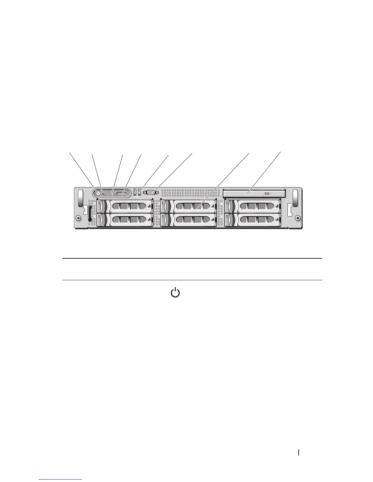
Figure 1-2 and Table 1-5 identify the controls, indicators, and connectors
located behind the optional rack bezel on the system's front panel.
Figure 1-2. Front-Panel Features and Indicators
Table 1-5. Front-Panel LED Indicators, Buttons, and Connectors
Item Indicator, Button,
or Connector
Icon Description
1 Power-on indicator,
power button
The power-on indicator lights when
the system power is on.
The power button controls the DC power
supply output to the system.
NOTE: If you turn off the system using
the power button and the system is running
an ACPI-compliant operating system,
the system performs a graceful shutdown
before the power is turned off. If the system
is not running an ACPI-compliant operating
system, the power is turned off immediately
after the power button is pressed.
6
5
4
3
2
1
87

 Loading...