7-6 Dell PowerEdge 4300 Systems Installation and Troubleshooting Guide
5HSODFLQJWKH)URQW%H]HO
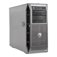
Use the following procedure to replace the front bezel of the computer:
1. Align the three clips on the edge of the bezel and press the bezel into place until
the tabs on the opposite edge of the bezel snap into place.
2. Reinstall the computer cover.
See “Replacing the Computer Cover” found earlier in this chapter.
$FFHVVLQJWKH,QWHULRURI<RXU&RPSXWHU
Accessing the interior of your computer requires disassembly of various components,
depending on the task that you need to perform. The following sections describe how
to disassemble computer components to access the Peripheral Component Intercon-
nect (PCI) and Industry-Standard Architecture (ISA) expansion cards, microprocessors
or memory module, system board, SCSI backplane board, and PSPB.
$FFHVVLQJWKH([SDQVLRQ &DUGV
The PowerEdge 4300 system provides an access door to the expansion card compart-
ment (see Figure 7-4) for easy installation and removal of the expansion cards. To
open the access door, the keylock must be in the latch position (designated by the
square icon) or the unlocked position (designated by the open lock icon).

 Loading...


