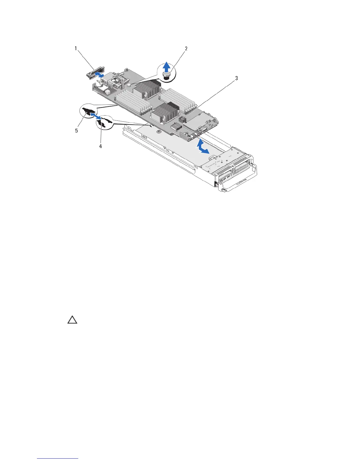
Figure 18. Removing and Installing the System Board
1. I/O connector cover
2. retention latch
3. system board
4. tabs on system chassis
5. slots in system board tray
Installing The System Board
1. Transfer the following components to the new system board:
a. internal USB key
b. storage controller card
c. SD vFlash card
d. memory modules and memory module blanks
e. processor(s) and heat sink(s), or processor filler blank
CAUTION: Ensure that the system board plate is parallel with the chassis.
2. Slide the new system board into the open end of the blade chassis until the retention latch engages.
When the board assembly is installed correctly, the tabs on the system board pan snap into the corresponding
openings in the floor of the blade chassis.
3. Replace the mezzanine card(s) in their original locations.
4. Reinstall the hard-drive/SSD backplane.
5. Replace the hard drive(s)/SSD(s).
If there are two drives, ensure that you reinstall them in their original locations.
6. Reinstall the cooling shroud.
7. Close the blade.
50