130 Installing System Components
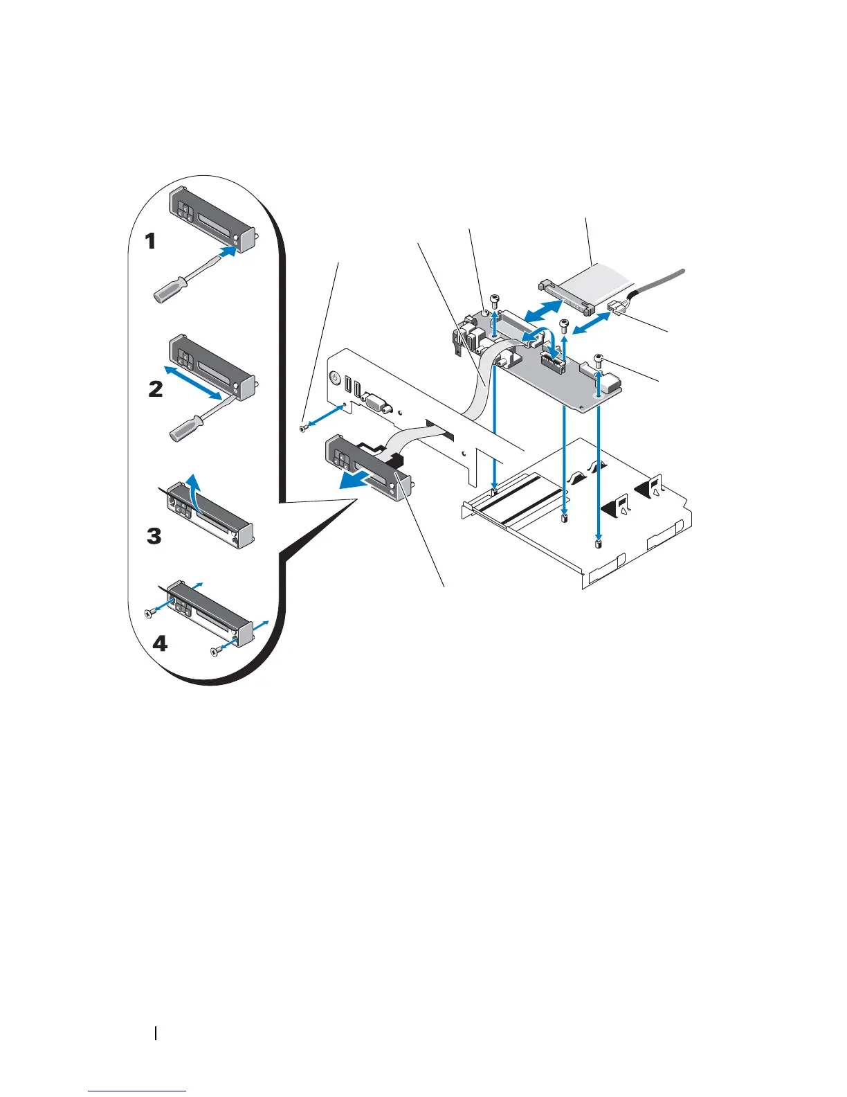
Figure 3-22. Control Panel Removal
16
Using a T10 Torx driver, remove the two screws that secure the display
module to the system chassis.
17
Remove the display module from the chassis cutout.
1 front panel screw (Torx) 2 display module cable
3 control panel board 4 control panel cable
5 USB cable 6 mounting screws (3 Torx)
7 display module

 Loading...


